Hydraulic multifrequency dynamic vibration absorber for rotary mechanical rotor

A technology of dynamic vibration absorber and rotating machinery, which is applied in the direction of mechanical equipment, rolling contact bearings, vibration suppression adjustment, etc. It can solve the problems that the real-time online continuous regulation of frequency cannot be realized, and achieve good vibration reduction effect, long service life and reliability. high effect

Active Publication Date: 2013-08-28
BEIJING UNIV OF CHEM TECH
View PDF10 Cites 37 Cited by
  • Summary
  • Abstract
  • Description
  • Claims
  • Application Information

AI Technical Summary

Problems solved by technology

[0009] To sum up, most of the current TMD frequency conversion devices change the natural frequency through the change of stiffness or damping. There are also frequency conversion TMDs used for veh...

Method used


Image

  • Hydraulic multifrequency dynamic vibration absorber for rotary mechanical rotor
  • Hydraulic multifrequency dynamic vibration absorber for rotary mechanical rotor
  • Hydraulic multifrequency dynamic vibration absorber for rotary mechanical rotor

Examples


Embodiment 1

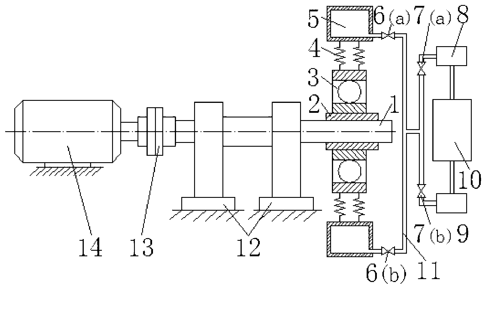
[0040] See attached Image 6 In some occasions, it is necessary to protect the bearing at the support 12 of the rotor system to avoid damage and destruction of the bearing, so it is necessary to install a hydraulic multi-frequency dynamic vibration absorber near the support 12. Give full play to the advantages of flexible and diverse application positions of the vibration absorber of the present invention, install hydraulic multi-frequency dynamic vibration absorbers at two different positions on the rotating shaft 1, that is, on the inner side of the two supports 12, and transfer the vibration energy to the TMD vibration absorber. The vibration of the rotating shaft 1 is reduced to achieve the purpose of protecting the bearing.

Embodiment 2

[0042] See attached Figure 7 , compared with Example 1, there is not enough space between the two supports 12 of some rotating shafts 1 to install the hydraulic multi-frequency dynamic shock absorber, and to achieve the same purpose of protecting the bearing, it can also be installed on the outer side of the two supports 12 . Although the installation position of the hydraulic multi-frequency dynamic vibration absorber is slightly changed, it can also protect the bearing. Therefore, in actual engineering applications, the installation position of the hydraulic multi-frequency dynamic vibration absorber can be flexibly selected according to specific conditions and needs.

Embodiment 3

[0044] See attached Figure 8 , for a flexible rotor with symmetrical applied loads, the midpoint between the two supports 12 has the largest deflection, so the unbalance here is relatively large, and when the rotating shaft 1 rotates, the vibration here will also be relatively large, in order to To reduce the vibration here, a hydraulic multi-frequency dynamic shock absorber can be installed here.


PUM


Abstract

The invention discloses a hydraulic multifrequency dynamic vibration absorber for a rotary mechanical rotor applicable to vibration control of multifrequency components of industrial rotary mechanical rotor systems of fans, compressors, turbines and machine tool spindle systems and the like, and belongs to the technical field of the vibration control. The hydraulic multifrequency dynamic vibration absorber comprises a connecting and transmitting mechanism, an adjustable tuning mass mechanism and a control system. The adjustable tuning quality mechanism comprises spring sets and mass blocks, the mass blocks are annual and hollow sealed cavities filled with water, oil or other high-density liquid medium and are connected with pumps and a recycling-liquid tank through a pipeline system, and mass of mass cavities is changed through liquid pumping and spraying of the pumps and frequency regulating is realized. The hydraulic multifrequency dynamic vibration absorber for the rotary mechanical rotor has the advantages of high reliability, stable performance, absence of worn parts, flexibility in adjustment, and thereby being applicable to the vibration of the multifrequency components and the like.

Description

technical field [0001] The invention relates to a rotor dynamic vibration absorber used in rotating machines, which is mainly used for controlling the vibration of rotating machine rotors such as fans, compressors, steam turbines, and spindle systems of processing machine tools, and belongs to the technical field of vibration control. technical background [0002] Rotating machinery such as fans, compressors, steam turbines, gas turbines, and processing machine tools have always been key equipment in modern large-scale industries. The high-speed rotating rotor is the core component, and its vibration and system stability affect the performance, reliability and reliability of rotating machinery products. important factor in service life. Therefore, how to reduce the vibration of the rotor system, improve the life of the rotor, and ensure the safe and reliable operation of mechanical equipment is of great significance in the research of rotating machinery. [0003] Tuned mass...

Claims


Application Information

Patent Timeline
IPC IPC(8): F16F15/173
CPCF16F15/027F16C27/04
Inventor 何立东张震坤张炳康杨秀峰高金吉
Owner BEIJING UNIV OF CHEM TECH
Why Eureka
Try Eureka