Engine tensioner and engine

An engine and tensioner technology, applied in mechanical equipment, transmissions, belts/chains/gears, etc., can solve problems such as tensioner function failure, timing system failure, damage to engine parts, etc., to simplify production and assembly process, the effect of avoiding accident damage

Active Publication Date: 2013-08-28
HANGZHOU DONGHUA CHAIN GRP
View PDF6 Cites 5 Cited by
  • Summary
  • Abstract
  • Description
  • Claims
  • Application Information

AI Technical Summary

Problems solved by technology

Once the tensioner is installed, if you forget to pull out the locking pin, the plunger will not pop out, and the function of the tensioner will fail. After the engine starts, due to the lack of tension in the chain, the severe vibration will quickly make the timing system invalid, and even damage the surrounding parts. engine parts

Method used


Image

  • Engine tensioner and engine
  • Engine tensioner and engine
  • Engine tensioner and engine

Examples


Embodiment 1

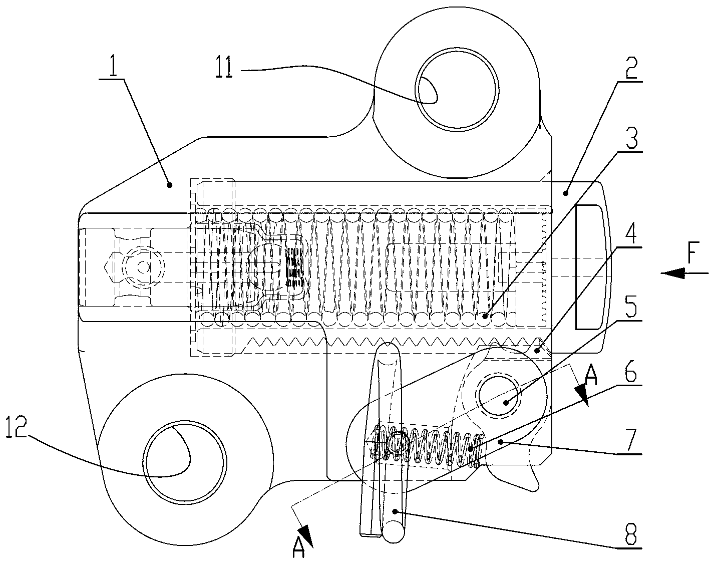
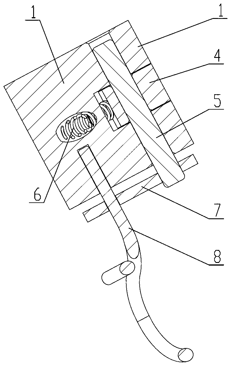
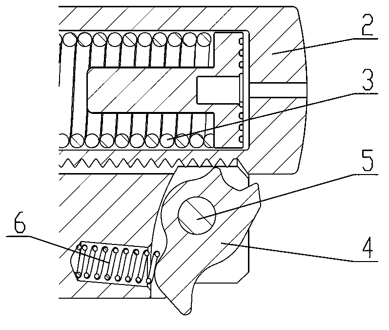
[0026] Such as Figure 5 , Figure 6 , Figure 7 The engine tensioner shown includes a housing 1, a plunger 2, a plunger spring 3, a pawl 4, a pawl pin 5 and a pawl spring 6, and the housing 1 is provided with a The two installation holes installed on the engine, the plunger spring 3 and the plunger 2 are inserted in the plunger hole of the housing 1, the pawl 4 is installed in the pawl groove of the housing 1 through the pawl pin 5, and the pawl The ratchet end of 4 can be engaged with the tooth groove on the plunger 2, the non-ratchet end of the ratchet 4 is against the ratchet spring 6, and the ratchet spring 6 is arranged in the ratchet spring hole of the housing 1, the ratchet Near the non-ratchet end of the pawl 4, a retaining pin 9 that limits the range of rotation of the pawl 4 is installed. The tooth grooves are engaged to limit the outward movement of the plunger 2. The retaining pin 9 is inserted in the retaining pin hole of the housing 1, and a positioning pin 1...


PUM


Abstract

The invention discloses an engine tensioner. A plunger spring and a plunger are inserted into a plunger hole of a casing, a pawl is arranged on the casing through a pawl pin, the ratchet end of the pawl can be meshed with a tooth groove disposed on the plunger, the non-ratchet end of the pawl abuts against the pawl spring, the pawl spring is arranged in a pawl spring hole disposed on the casing, and a keeping pin used for limiting the rotating range of the pawl is arranged at the position close to the non-ratchet end of the pawl. When the non-ratchet end of the pawl abuts against the keeping pin, and the ratchet end of the pawl is meshed with the tooth groove disposed on the plunger so as to limit the plunger to move outwards. The keeping pin is inserted into a keeping pin hole of the casing, a positioning pin is inserted into an installation hole of the casing, the front end of the positioning pin penetrates out of the casing, and the back end of the positioning pin is fixedly connected with the keeping pin through a locking piece. The invention further discloses an engine with the tensioner. A locking structure is simple and fast, convenient to assemble and install without failure, accident damages caused by the fact that a locking assembly is pulled out in advance or is forgotten to be pulled out are totally avoided.

Description

technical field [0001] The invention relates to an engine, in particular to an engine tensioner. Background technique [0002] Engine tensioners in the prior art such as figure 1 , figure 2 As shown, it includes a housing 1, a plunger 2, a plunger spring 3, a pawl 4, a pawl pin 5 and a pawl spring 6, and the housing 1 is installed and fixed on the front of the engine through two mounting holes 11, 12 and bolts. Near the chain, the plunger spring 3 and the plunger 2 are inserted in the plunger hole of the housing 1, the pawl 4 is installed in the pawl groove of the housing 1 through the pawl pin 5, and the ratchet end of the pawl 4 can be Engaging with the tooth groove on the plunger 2 , the non-ratche end of the pawl 4 is against the pawl spring 6 , and the pawl spring 6 is arranged in the pawl spring hole of the housing 1 . In order to prevent the plunger 2 from popping up when the tensioner is not installed or in a non-working state, it is necessary to set a locking st...

Claims


Application Information

Patent Timeline
Patent Type & Authority Applications(China)
IPC IPC(8): F16H7/08
Inventor 邢建恒叶斌卢旭东王洪军宣碧华
Owner HANGZHOU DONGHUA CHAIN GRP
Why Eureka
Try Eureka