Drive circuit suitable for silicon controlled rectifier of rectifier circuit of frequency converter

A technology for rectifying circuits and driving circuits, applied in the field of circuits, can solve problems such as complex installation, and achieve the effects of reducing losses, reducing the cost of the whole machine, and simplifying the production and assembly process.

Inactive Publication Date: 2021-08-31
深圳弘远电气有限公司
View PDF6 Cites 3 Cited by
  • Summary
  • Abstract
  • Description
  • Claims
  • Application Information

AI Technical Summary

Problems solved by technology

[0004] Aiming at the deficiencies of the prior art, the present invention provides a drive circuit suitable for the rectifier circuit of the frequency converter, which solves the problems caused by the long-term use of uncontrollable rectification diodes and DC contactors as the rectification soft-start circuit of the frequency converter. installation complexity

Method used


Image

  • Drive circuit suitable for silicon controlled rectifier of rectifier circuit of frequency converter
  • Drive circuit suitable for silicon controlled rectifier of rectifier circuit of frequency converter
  • Drive circuit suitable for silicon controlled rectifier of rectifier circuit of frequency converter

Examples


Embodiment

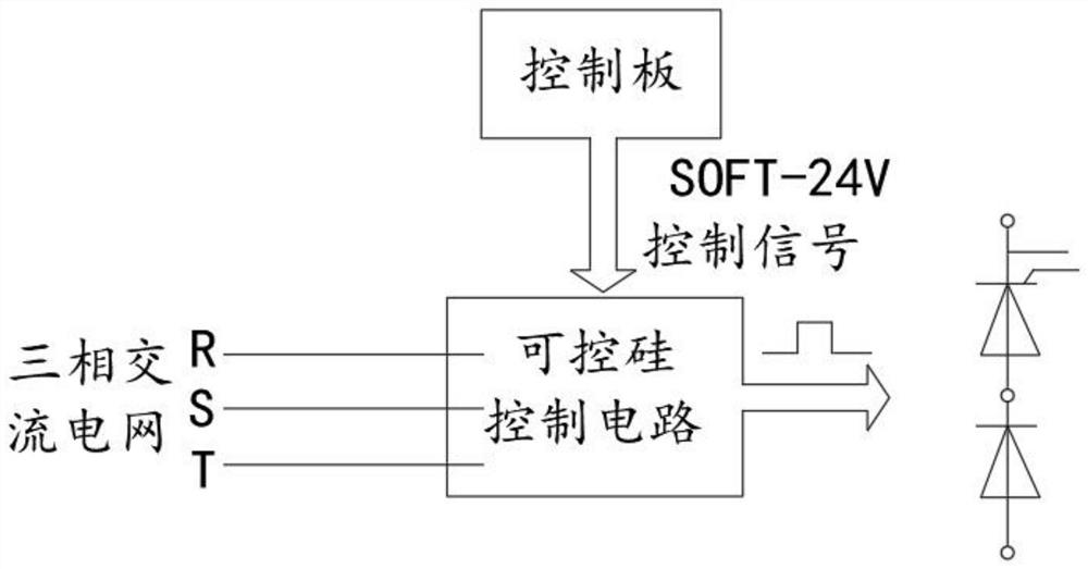
[0022] Such as figure 1 As shown, a drive circuit suitable for the thyristor of the inverter rectifier circuit, the circuit includes:

[0023] The thyristor control circuit controls the on and off of the diode according to the phase of the input AC voltage;

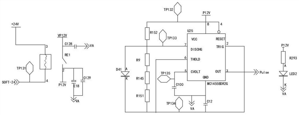
[0024] The control board controls the signal of the thyristor control circuit through the SOFT control signal;

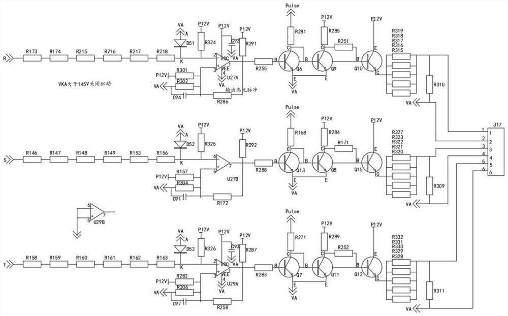
[0025] The R-phase circuit is controlled by the thyristor control circuit as a whole to ensure that the gate of the thyristor has received the pulse driving voltage before the sine wave voltage crosses zero, avoiding the large loss and heat generation caused by high reverse voltage;

[0026] The S-phase circuit is controlled by the thyristor control circuit as a whole to ensure that the gate of the thyristor has received the pulse driving voltage before the sine wave voltage crosses zero, which avoids the great loss and heat generation caused by high reverse voltage;

[0027] The T-phase circuit is controlled...


PUM


Abstract

The invention provides a drive circuit suitable for a silicon controlled rectifier of a rectifier circuit of a frequency converter, and relates to the technical field of circuits. A silicon controlled rectifier control circuit can control the on and off of a diode according to the phase of an input alternating voltage, a control panel performs signal control on the silicon controlled rectifier control circuit through an SOFT control signal, and an R-phase circuit, an S-phase circuit and a T-phase circuit are is integrally controlled by the silicon controlled rectifier control circuit, so that a silicon controlled rectifier gate level receives pulse driving voltage before sine-wave voltage passes zero, and heating caused by great loss generated by wave generation at high reverse voltage is avoided; the silicon controlled rectifier control circuit is used for controlling the S-phase circuit, the R-phase circuit and the T-phase circuit, a rectification soft start loop is formed by adding a diode, and the silicon controlled rectifier controls the on and off of the diode according to the phase of the input AC voltage, so that the loss of the silicon controlled rectifier is reduced, the production and assembly process of the product is simplified, and the cost of the whole machine is reduced.

Description

technical field [0001] The invention relates to the field of circuit technology, in particular to a drive circuit suitable for a thyristor in a rectifier circuit of a frequency converter. Background technique [0002] Under normal circumstances, the power grid needs to provide voltage to the motor of the electrical equipment, so that the motor can drive the electrical equipment to work; but for example, when the lifting equipment is lowered, the lifting equipment will drive the motor to rotate under the action of inertia, etc., resulting in The regenerative electric energy is fed back to the grid. In occasions where the mechanical load is relatively heavy and the braking speed is required to be very fast, etc., the regenerative electric energy generated by the motor is large, which may cause damage to the power grid or electrical equipment. Therefore, the braking resistor can be controlled by the inverter control circuit to consume the regenerative power electrical energy. ...

Claims


Application Information

Patent Timeline
Patent Type & Authority Applications(China)
IPC IPC(8): H02M1/06H02M1/36H02M7/155
CPCH02M1/06H02M1/36H02M7/1552H02M7/1555
Inventor 龚耀京杨运海张荣亮臧绍敢
Owner 深圳弘远电气有限公司
Why Eureka
Try Eureka