Extremely-simple type hydraulic rotary buffer

A technology of hydraulic rotation and buffer, applied in the direction of liquid resistance brakes, brake types, seat or cover for toilets, etc., can solve the problems that damping oil cannot pass through or is slow, increase assembly cost, high manufacturing cost and assembly cost, etc. Achieve the effect of simple and reliable structure and function, stable damping oil pressure, and easy production and assembly

Pending Publication Date: 2020-10-16
厦门精熠工贸有限公司
View PDF3 Cites 4 Cited by
  • Summary
  • Abstract
  • Description
  • Claims
  • Application Information

AI Technical Summary

Problems solved by technology

[0003] For example, a Chinese utility model patent (CN205729235U) discloses a damper, which includes a shaft housing 5 with ribs 55 on the inner wall and a shaft core 7 with ribs 74 on the radial surface, and blade grooves on each rib 74 75 add a vane 6, so that the oil-passing check valve is formed between the shaft core 7 and the inner wall of the shaft housing 5. The setting of the vane groove 75 needs to increase the thickness of the rib 74 in the rotation direction, so that the vane 6 has a swing space. The increase of the thickness of the convex rib 74 will make the rotation range of the convex rib 74 between the two retaining ribs 55 in the shaft housing 5 smaller, and the maximum angle of opening the toilet cover plate will be reduced, and the cover plate will be turned upright. Insufficient angle will cause the center of gravity to move forward and stand unstable
[0004] For example, a Chinese utility model patent (CN210265675U) discloses a damping mechanism with the function of receding and quieting, including a housing 20 filled with damping oil, a rotating shaft 10 that is sealed and rotated with the housing 20 to disturb the damping oil, and the rotating shaft 10 One of the two of the housing 20 is provided with a swinging paddle 22, so that an oil check valve is formed between the rotating shaft 10 and the inner wall of the housing 20; the rotating shaft 10, housing 20 and paddle of this damping mechanism The structure of 22 is all comparatively complicated, and assembly is inconvenient, makes manufacturing cost and assembly cost higher
[0005] For another example, a damper disclosed in the Chinese invention patent (CN106937842A) includes a shaft shell 1 and a shaft core 2, and one end of the shaft core 2 is inserted into the shaft shell 1 and can rotate relative to the shaft shell 1. There is at least one inner convex strip 1-3, the outer wall of the shaft core is provided with at least one partition rib 3-3, the shaft shell 1 is filled with damping liquid, and the shaft end of the shaft core 3 in the shaft shell 1 is provided with an additional The blade 2 rotated by the shaft core 3, through the differential coupling between the blade 2 and the shaft core 3, the blade 2 generates rotational differential when the shaft core 3 rotates in one direction, staggers the gap to generate oil to realize the non-damping rotation function, and When rotating in the opposite direction, the blade 2 does not produce a differential motion on the shaft core 3, so that the damping oil between the blade 2 and the shaft core 3 cannot pass through or slowly passes through, so that hydraulic damping is generated in the shaft shell to brake the shaft core 3 and the blade 2 to rotate slowly , to realize the function of damping rotation; this damper shaft housing 1 adds blades 3 installed on the shaft end of the shaft core 2 to build an oil-passing check valve, which not only increases the production cost, but also increases the assembly cost, and the structure is still not simple enough

Method used


Image

  • Extremely-simple type hydraulic rotary buffer
  • Extremely-simple type hydraulic rotary buffer
  • Extremely-simple type hydraulic rotary buffer

Examples


Embodiment 1

[0036] Embodiment 1 (flexible oil wing without cavity, single concave surface).

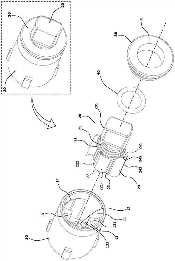
[0037] Such as figure 1 and figure 2 A minimalist hydraulic rotary buffer shown is only composed of a shaft sleeve 10 , a rotating shaft 20 , a gland 30 and a sealing ring 40 .

[0038] Such as Figure 1 to Figure 5 As shown, the shaft sleeve 10 of the present invention is integrally injection molded. The shaft sleeve 10 has an oil chamber 11, and two partition ribs 13 connected to the bottom surface 12 of the chamber are symmetrically arranged on the wall of the oil chamber 11. The axial top ends of the partition ribs 13 are partition ribs The top surface 131 of the rib 13 is an oil-separating surface 132 at the radial end of the rib 13; two arc-shaped platform sections 14 are arranged on the oil chamber 11 wall on the symmetrical side of the two ribs 13, and the bottom surface 12 of the oil chamber 11 It has a central hole 15, and the bottom surface 12 of the cavity is provided with a fast oi...

Embodiment 2

[0055] Embodiment two (the oil wing has cavity, double concave surface).

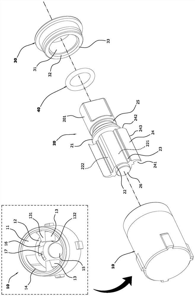
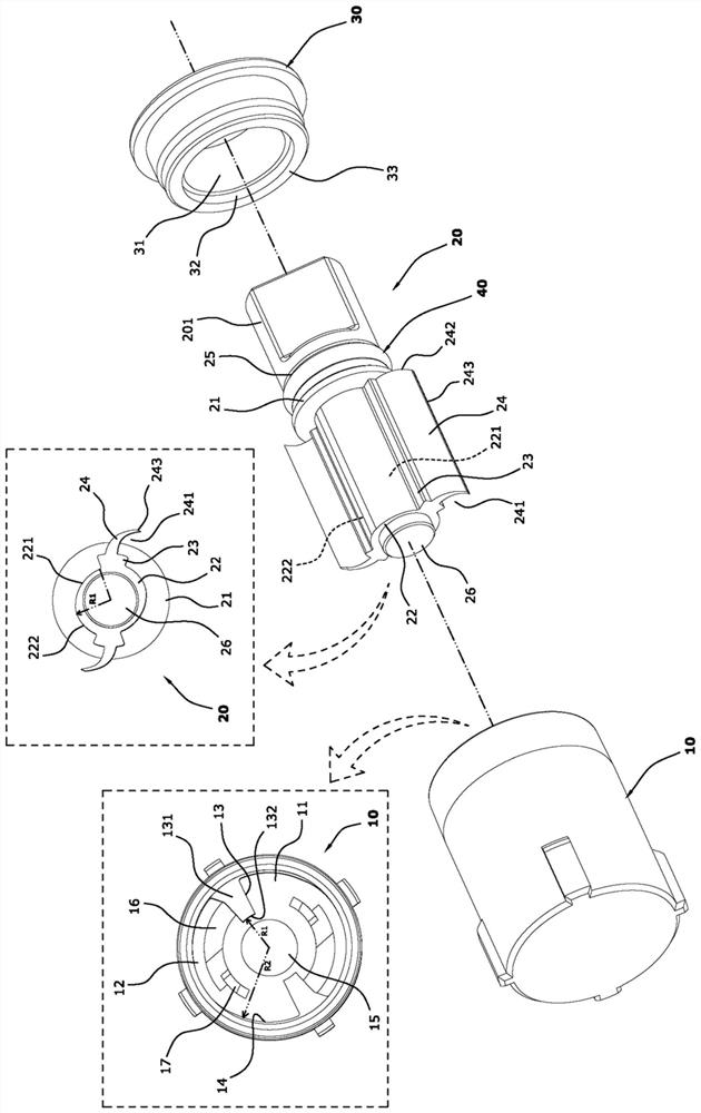
[0056] Such as Figure 9 ~ Figure 13As shown, the difference between the present embodiment and the first embodiment is that the oil deflection wing 24 of the present embodiment has two concave surfaces 241 for deflecting the oil, a top edge surface 242 that is in contact with the inner end surface 33, and an arc-shaped platform section 14 Elastic press-contact fits the wing end 243, and the oil wing 24 also has a cavity 244 to increase its flexural deformation elasticity; in this way, the rotating shaft 20 is inserted into the sleeve 10, and the concave surface 241 of the oil wing 24 is no longer identified Whether or not it faces the arc-shaped platform section 14, the assembly efficiency is improved; and the cavity 244 is added to the oil wing 24, which can increase the elasticity and elastic sensitivity of the oil wing 24, and also increase the speed of its shape recovery. Other structures, working...


PUM


Abstract

The invention discloses an extremely-simple type hydraulic rotary buffer. The extremely-simple type hydraulic rotary buffer only comprises a shaft sleeve, a rotating shaft, a gland and a sealing ring,the shaft sleeve is symmetrically provided with two separation ribs connected with a cavity bottom surface, and two arc-shaped table sections are arranged on the oil cavity wall on one sides of the two symmetric separation ribs; a convex ring and an inner shaft section of the rotating shaft sleeve an oil cavity, two convex strips are symmetrically arranged on the inner shaft section, each convexstrip is provided with an elastic flexible oil wing, and the flexible oil wings are separated from the oil cavity wall or are elastically pressed against the arc-shaped table sections in a contactingmode; the oil cavity is fixed to the oil cavity in a pressing connection mode, the convex ring sleeves a step hole in the inner end face of the gland, the inner side face and the inner end face of theconvex ring are flush with the top surfaces of the separation ribs in a flush manner, and the flexible oil wings make contact sliding fit with the inner end face; the shaft sleeve and the gland is sealed by the sealing ring, the flexible oil wings, the oil cavity wall, and the arc-shaped table sections form a one-way oil passing switch for controlling the rotating speed of the rotating shaft. Theextremely-simple type hydraulic rotary buffer is ingenious in design, can realize one-way damping rotation, automatic voltage regulation and overload protection functions, does not need to add othercomponents, and is simple and reliable in structure function and low in production and manufacturing cost.

Description

technical field [0001] The invention relates to a hydraulic one-way damper for a toilet cover hinge, in particular to a very simple hydraulic rotary buffer. Background technique [0002] Most of the existing toilet cover hinges are equipped with a hydraulic damping rotary buffer. The hydraulic damping rotary buffer basically includes a cylinder filled with damping oil and a rotating shaft inserted into the cylinder to seal the oil. After reaching a certain angle, the hydraulic damping brake cover plate slowly falls. The basic design is to install at least one part in the cylinder and the shaft sealing section to build the oil-passing check valve, so that the shaft rotates relative to the cylinder for one stroke and then passes the oil. The one-way valve is closed, and the oil pressure damping is generated in the barrel to brake the rotating shaft to rotate slowly. [0003] For example, a Chinese utility model patent (CN205729235U) discloses a damper, which includes a shaft ...

Claims


Application Information

Patent Timeline
Patent Type & Authority Applications(China)
IPC IPC(8): F16D57/00A47K13/24E05F3/14E05F3/20
CPCA47K13/24E05F3/14E05F3/20F16D57/00F16D57/005
Inventor 王治恭
Owner 厦门精熠工贸有限公司
Why Eureka
Try Eureka