Self-pumping fluid-dynamic-pressure-type mechanical seal

A fluid dynamic pressure, mechanical seal technology, applied in the direction of engine seals, mechanical equipment, engine components, etc., can solve the complex structure of the sealing end face of the double-row spiral groove mechanical seal, the poor anti-particle interference ability, and the small opening force of the sealing end face. and other problems, to achieve the effect of superior sealing performance, reducing operating costs, and avoiding abrasive wear

Active Publication Date: 2013-08-28
NANJING FORESTRY UNIV
View PDF7 Cites 32 Cited by
  • Summary
  • Abstract
  • Description
  • Claims
  • Application Information

AI Technical Summary

Problems solved by technology

[0003] The purpose of the present invention is to propose a self-pumping mechanical seal with a hydrodynamic pressure effect suitable for a wide range of fluid pressure difference on both sides of the sealing end face, so as to solve the problem of the existing single-row spiral groove mechanical seal end face with small opening force and large leakage rate , Poor anti-particle interference ability, complex sealing end face structure of double-row spiral groove mechanical seal, and large installation space. Under the same conditions, it has greater working flexibility and zero leakage than the above-mentioned seal.

Method used


Image

  • Self-pumping fluid-dynamic-pressure-type mechanical seal
  • Self-pumping fluid-dynamic-pressure-type mechanical seal
  • Self-pumping fluid-dynamic-pressure-type mechanical seal

Examples


Embodiment 1

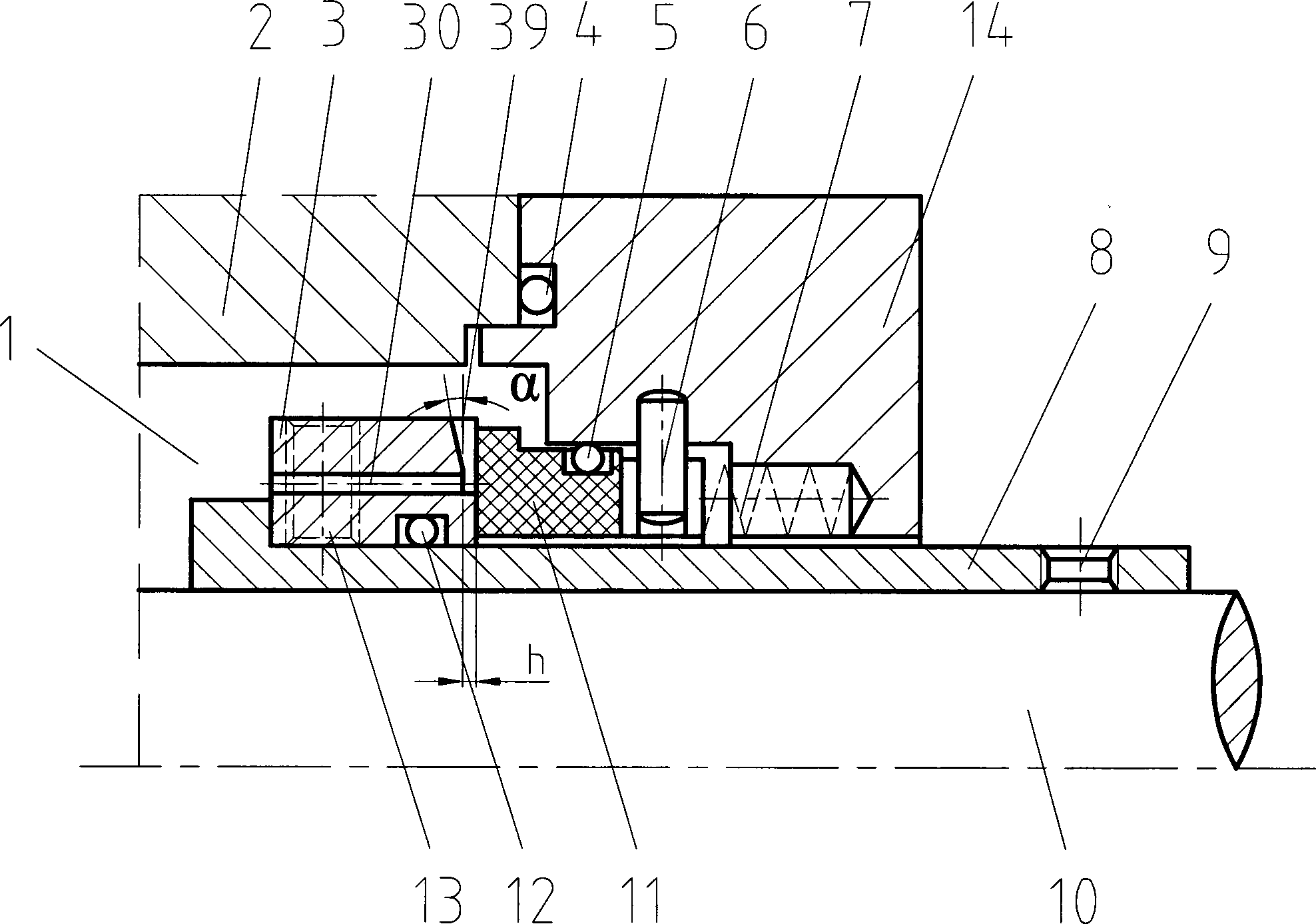
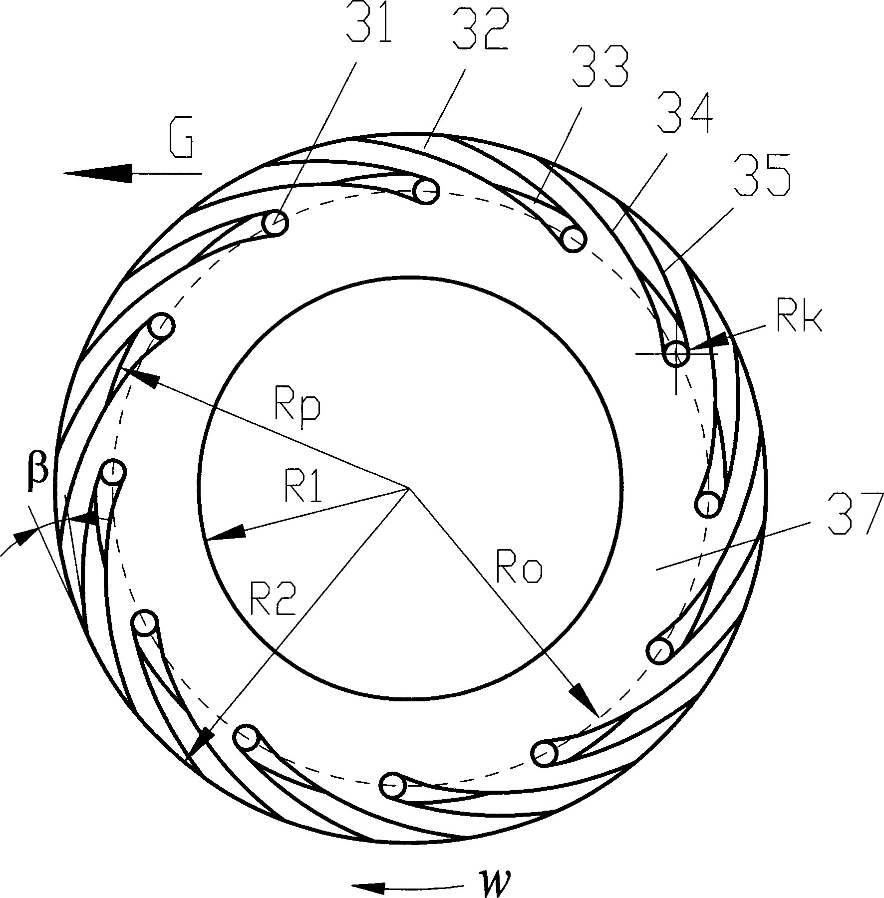
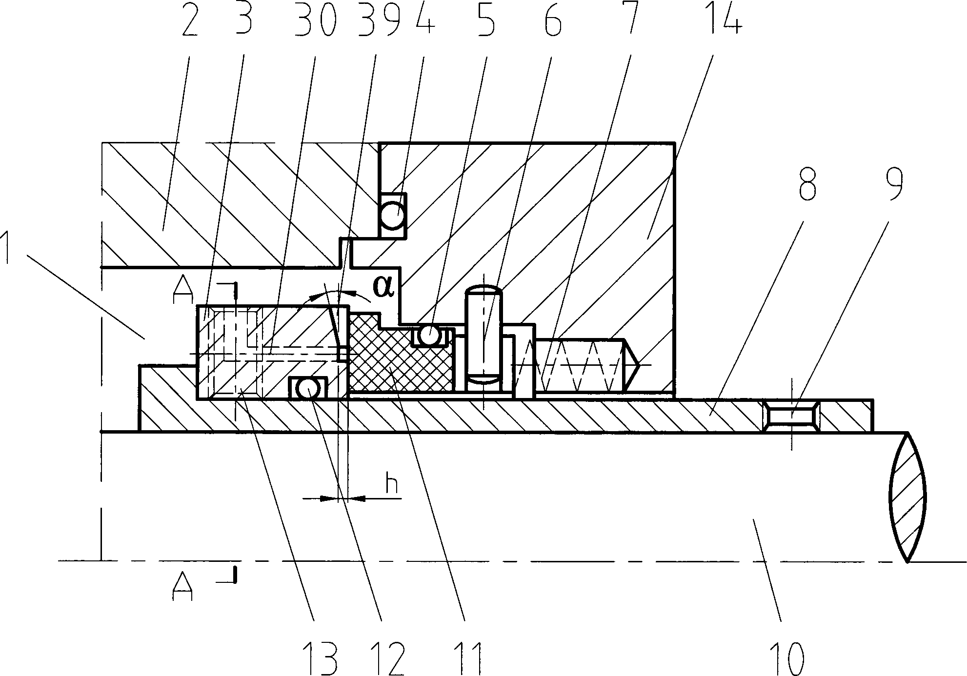
[0049] figure 1 with figure 2 A self-pumping fluid dynamic pressure mechanical seal is described, which is arranged between the casing 2 of the rotating machine and the shaft 10 or the sleeve 8, and consists of a moving ring 3, an O-ring 12 for the moving ring, a static ring 11, The static ring is composed of an O-ring 5, a spring 7, and a static ring seat 14; On the outer part of the end face; 12 sets of back-curved fluid-type grooves 39 are set in the groove area, and the sealing surface between the backward-curved fluid-type grooves 39 forms a sealing weir;

[0050] The back-curved fluid groove 39 includes two parts: a slope groove 32 and a flat groove 33. The slope groove 32 is located at the large radius portion of the end face of the moving ring, and the flat groove 33 is located at the small radius portion of the end face of the moving ring;

[0051] The outlet of the back-curved fluid groove 39 is located at the outer diameter of the moving ring sealing surface, the...

Embodiment 2

[0059] Figure 3 to Figure 5 It is another self-pumping hydrodynamic mechanical seal, the difference from Embodiment 1 is that the inlet 31 of the backward-curved fluid groove 39 in this embodiment and the circular seal set in the middle of the sealing surface of the moving ring 3 The ring groove 36 is connected, and the circular ring groove 36 is provided with 6 axial and radial combination channels 30 communicating with the sealing chamber 1; The cross-section of the joint of the surface is a wedge-shaped opening 38; the circular ring groove 36 has the functions of collecting self-lubricating, self-flushing medium and preventing the pumping medium from being uneven and the fluid replenishment at the inlet 31 of the back-curved fluid type groove 39 is not timely Cavitation occurs.

[0060] The rest of the structures and implementations are the same as in Embodiment 1.


PUM


Abstract

The invention relates to a self-pumping fluid-dynamic-pressure-type mechanical seal. More than three groups of backwards-bent-type fluid grooves are formed in the moving ring seal end surface of the self-pumping fluid-dynamic-pressure-type mechanical seal, wherein each fluid groove is composed of a slope groove and a horizontal groove, the outlet of each fluid groove is located outside the moving ring seal end surface, and the inlet of each fluid groove is located in the middle of the moving ring seal end surface, and is communicated with a sealing cavity through an axial hole passage or an axial and radial combined hole passage on a moving ring. When the moving ring rotates, media in each fluid groove are accelerated to be high-speed fluid, the high-speed fluid flows to the outer diameter side of the moving ring and is pumped into the sealing cavity under the action of centrifugal force and forms a low-pressure area in the inlet of each backwards-bent-type fluid groove, and media in the sealing cavity flow into each backwards-bent-type fluid groove through the axial hole passage or the axial and radial combined hole passage under the action of pressure difference, wherein the axial hole passage or the axial and radial combined hole passage is arranged on the moving ring, and is communicated with the sealing cavity so as to form a new self-pumping cycle. In the process that the high-speed fluid is pumped out, the flowing speed is reduced, the pressure is increased, and certain opening force is formed as the circulating sectional area gradually increases. The self-pumping fluid-dynamic-pressure-type mechanical seal has good self-lubricating, self-washing and anti-solid-particle-interference ability and superior sealing performance.

Description

technical field [0001] The invention belongs to the technical field of sealing, in particular to a self-pumping mechanical seal with hydrodynamic pressure effect, which is suitable for sealing the rotating shafts of various compressors, centrifugal pumps, reactor stirrers and other rotating machines. Background technique [0002] At present, non-contact mechanical end seals are widely used in centrifugal compressors, fans, centrifugal pumps and other equipment in petroleum, chemical, chemical fiber, papermaking, electric power and metallurgical industries. The principle of hydrodynamics forms a hydrodynamic wedge, which generates the opening force of the end face, and achieves the purpose of reducing the wear of the sealing end face. For example, a hydrodynamic and static pressure combined non-contact mechanical seal with a single row of spiral grooves disclosed in US US4212475, China ZL00239203. 8 discloses a single-row fluid type groove upstream pumping mechanical seal and...

Claims


Application Information

Patent Timeline
Patent Type & Authority Applications(China)
IPC IPC(8): F16J15/54F16J15/40
CPCF16J15/342F16J15/002F16J15/3412
Inventor 孙见君王敏周敏涂桥安海乐檬李志宏李正新王鑫王衍
Owner NANJING FORESTRY UNIV
Why Eureka
Try Eureka