

Magnetic moment orientation device for identifying magnetic graph on magnetic stripe and identification method of magnetic moment orientation device
A magnetic and magnetic stripe technology, used in character and pattern recognition, banknote authenticity inspection, instruments, etc., can solve the problems of limiting the anti-counterfeiting ability of RMB, unable to detect the magnetic moment orientation of magnetic medium materials, and low ability to identify the authenticity of RMB. , to achieve the effect of suppressing common mode magnetic field interference, improving anti-counterfeiting ability, and strong common mode magnetic field interference
- Summary
- Abstract
- Description
- Claims
- Application Information
AI Technical Summary
Problems solved by technology
Method used
Image

Examples
Embodiment 1
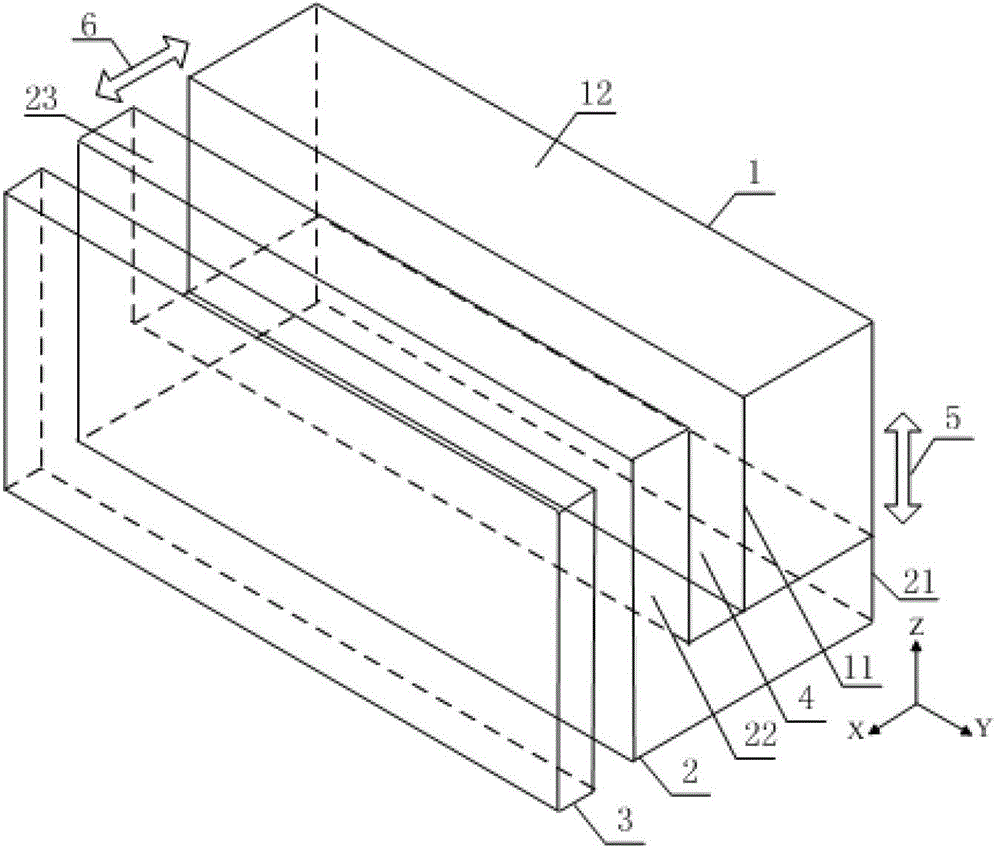
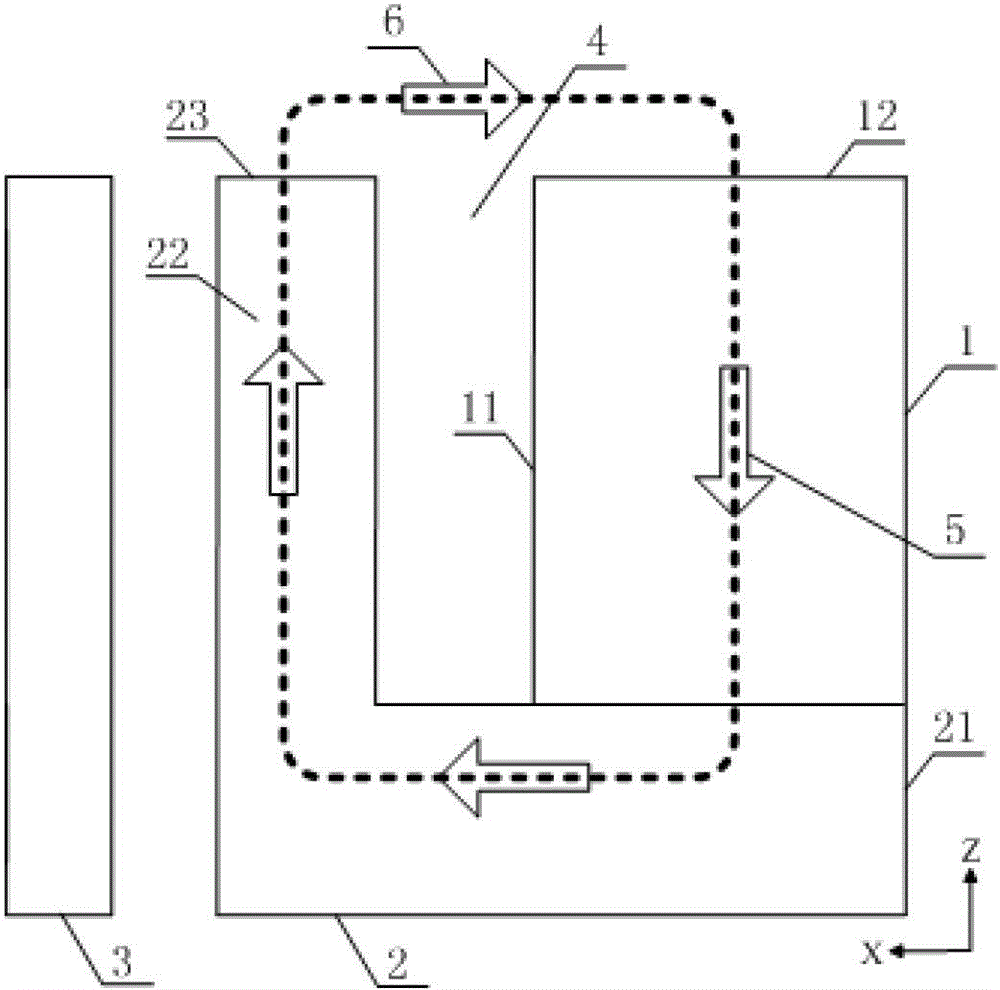
[0038] The magnetic moment orientation device for identifying the magnetic pattern on the magnetic strip provided by the present embodiment includes a permanent magnet 1, an L-shaped soft magnetic body 2 and a magnetoresistive chip 3, such as figure 1 and figure 2 shown. The soft magnet 2 includes a bottom 21 and side walls 22 . In this embodiment, the sidewalls 22 of the permanent magnet 1 and the soft magnet 2 are, for example, rectangular parallelepiped. The permanent magnet 1 is arranged on the bottom 21 of the soft magnet 2 . One side 11 of the permanent magnet 1 faces the side wall 22 of the soft magnet 2 , and a slit 4 is formed between the side 11 of the permanent magnet 1 and the side wall 22 of the soft magnet 2 . The magnetoresistive chip 3 is disposed outside the sidewall 22 of the soft magnetic body 2 . The magnetization direction 5 of the permanent magnet 1 is perpendicular to the bottom 21 of the soft magnetic body 2 , that is, the magnetization direction ...
Embodiment 2
[0047] The magnetic moment orientation device for identifying the magnetic pattern on the magnetic strip provided by the present embodiment includes a permanent magnet 1, an L-shaped soft magnetic body 2 and a magnetoresistive chip 3, such as Figure 8 and Figure 9 shown. The soft magnet 2 includes a bottom 21 and side walls 22 . The permanent magnet 1 is arranged on the bottom 21 of the soft magnet 2 . One side 11 of the permanent magnet 1 faces the side wall 22 of the soft magnet 2 , and a slit 4 is formed between the side 11 of the permanent magnet 1 and the side wall 22 of the soft magnet 2 . In this embodiment, a first inclined surface 13 is provided between the side surface 11 of the permanent magnet 1 and its upper end surface 12 , and a second inclined surface 24 is provided between the inner surface 25 of the side wall 22 of the soft magnetic body 2 and its upper end surface 23 . The first slope 13 and the second slope 24 are in an inverted "eight" shape. The mag...
PUM
 Abstract
Description
Claims
Application Information