
Anti-counterfeiting fiber with fluorescence fiber color changing with the change of optic angle of exciting light and anti-counterfeiting material

An anti-counterfeiting fiber and photoluminescent material technology, which is applied in fiber raw material processing, fiber chemical characteristics, non-fiber pulp addition, etc., can solve the problems of fiber luminous color change, unknown effect of excitation light angular discoloration, inability to overcome influence and other problems

Active Publication Date: 2009-09-02
SHANGHAI KOS SECURITY PAPER TECH CO LTD
View PDF1 Cites 24 Cited by
  • Summary
  • Abstract
  • Description
  • Claims
  • Application Information

AI Technical Summary

Problems solved by technology

[0006] First of all, the patent does not mention any unique visual characteristics that the structure can have—that is, the visual effect brought about by the optical characteristics that the change of the excitation light irradiation angle will lead to the change of the luminous color, and it does not explain what the purpose of the invention is to solve. , and did not explain its inventive effect
In fact, unless there is a deep light-emitting principle of photoluminescent materials (or the inventor has specific actual production)-that is, the principle that the light-emitting material absorbs the excitation light while being irradiated by the excitation light, plus other A series of inferences can lead to the conclusion that the change of the excitation light irradiation angle will lead to the change of the luminous color of the structural fiber. It is difficult to imagine this conclusion given the structure by a single review
[0007] Second, the discoloration effect of the excitation light angle of the fiber itself must be reflected in the paper to be valuable, so the structure must first solve the problem that the fiber is in the same direction after being copied into the paper. In this patent embodiment, The fibers are straight lines, and the orientation of such fibers into the paper relative to the paper surface is extremely chaotic. The specific papermaking experiments have proved that the fibers on the surface of the paper (not considering the fibers embedded in the pulp layer, or the paper-making pressure) process compression deformed fiber) only 15% can produce light angle discoloration, which makes the structural fiber useless, but more likely to cause misjudgment
Copying into paper to solve the problem of orientation requires three logical thinking steps: 1. What kind of shape has a stable orientation? 2. What kind of orientation should the fiber cross-section face on the paper to change the color of the excitation light angle for the best effect? 3. How to achieve 100% directional bending of each fiber in the desired direction? Since it is inferred that the inventor of the patent did not know that the structure would produce the effect of excitation light angle discoloration, it is impossible to talk about the following inferences
[0008] Third, the photochromic fiber is copied into the paper. The inventor has also found and concluded in a large amount of practice that when the fiber is copied into the paper, there are two major factors that affect the photochromic effect: one is when the fluorescent fiber is embedded in the pulp When the paper fiber is in the layer of paper fiber, the paper fiber attached to the fluorescent fiber will produce diffuse reflection to the directional irradiation excitation light, so that the direction of the excitation light actually irradiated on the fluorescent fiber will change, and the more the fluorescent fiber is embedded in the pulp layer Deep, the more serious this diffuse reflection is, the worse the directionality of the excitation light will be, which will seriously affect the light angle discoloration effect and cause the discoloration effect to disappear. If it is not overcome, it will be of no practical value; the second factor It is because the photochromic fiber has a compression process in the process of copying into the paper. This compression process will cause the fiber cross section to become flat, which will also seriously affect the photochromic effect and cause the discoloration effect to disappear. If you do not try to overcome it, Can have no practical value; The side-by-side shape (circle shape) fiber described in the claim of the invention all proves in the inventor's theoretical analysis and a large amount of concrete practice, and this two-component side-by-side structure cannot overcome the influence of above-mentioned two major factors of
[0009] To sum up the above, the patent not only did not solve this worldwide problem, but also did not take solving this problem as the purpose of the invention, and at the same time, it did not propose many specific methods necessary to solve this problem

Method used


Image

  • Anti-counterfeiting fiber with fluorescence fiber color changing with the change of optic angle of exciting light and anti-counterfeiting material
  • Anti-counterfeiting fiber with fluorescence fiber color changing with the change of optic angle of exciting light and anti-counterfeiting material
  • Anti-counterfeiting fiber with fluorescence fiber color changing with the change of optic angle of exciting light and anti-counterfeiting material

Examples


Embodiment 1

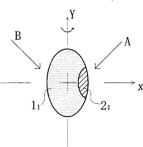
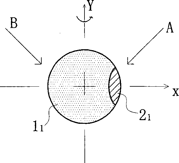
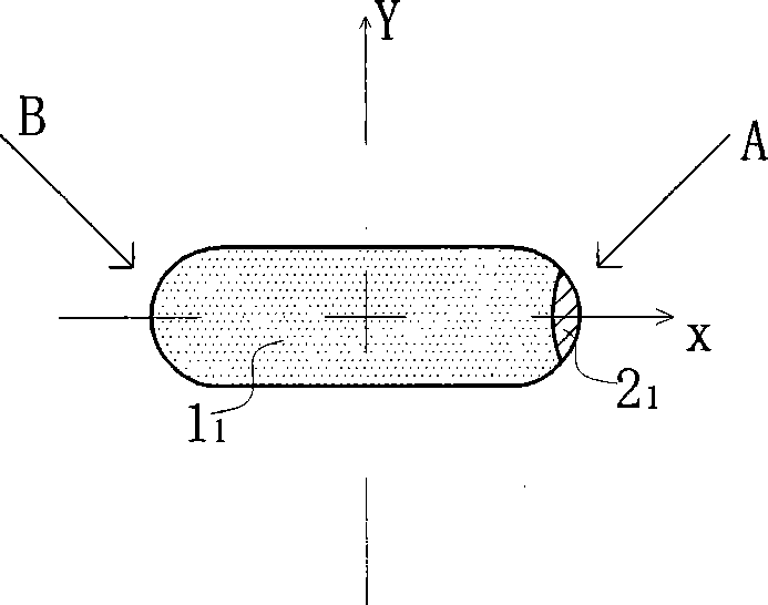
[0097] Example 1: Figure 1a , Figure 1b , Figure 1c , Figure 1d , Figure 1e , Figure 1f is a cross-sectional view of a two-component fiber with one component containing luminescent material.

[0098] The cross-section of the fiber consists of the barrier component 1 1 and luminescent component 2 1 Composite composition of two components, the two components are distributed side by side on the cross section, and extend in parallel without twisting in the fiber length direction. Barrier component 1 1 It is an absorbing material that does not contain photoluminescent material, can transmit visible light and block excitation light, and the absorption spectrum in the absorbing material includes at least the excitation wavelength of the luminescent material; luminescent component 2 1 The photoluminescent material M is contained in the cross-section, which is located on one side of the vertical axis Y-axis, and the horizontal axis X-axis of the cross-section bisects the p...

Embodiment 2

[0105] Example 2: with Figure 2a , Figure 2b The cross-section of the fiber consists of the first luminescent component 2 2 and the second luminescent component 3 2 The two components are side by side and compounded. The two components are distributed side by side on the cross section, and extend in parallel without twisting in the fiber length direction. Since the flatness of the fiber cross section is ≤ 1, the expressed fiber is a two-component bend. Fiber, first luminescent component 2 2 Contains photoluminescent material M, the second luminescent component 3 2 contains photoluminescent material N, the luminescent color of photoluminescent material M and photoluminescent material N have the same excitation light wavelength, but the luminescent color M and luminescent color N have obvious visual differences; the two components are respectively Located on one side of the vertical axis Y-axis, the horizontal axis X-axis of the cross-section bisects the two components in ...

Embodiment 3

[0110] Example 3: Figure 3a , Figure 3b , Figure 3c , Figure 3d , Figure 3e , Figure 3f is a cross-sectional view of a three-component fiber in which two components contain luminescent material,

[0111] The above-mentioned is an absorbing material that does not contain photoluminescent material, can pass through visible light and can block excitation light. The absorption spectrum in the absorbing material includes the excitation wavelength of the luminescent material. The first luminescent component 2 3 Contains photoluminescent material M, the second luminescent component 3 3 contains photoluminescent material N, and the luminescent color of photoluminescent material M has the same excitation light wavelength as photoluminescent material N, but the luminescent color has obvious visual difference. In the cross section, the first luminescent component 2 3 and the second luminescent component 3 3 Located on both sides of the Y-axis, each figure of Example 3 shows th...


PUM

PropertyMeasurementUnit
lengthaaaaaaaaaa

Abstract

The invention provides an anti-counterfeiting fiber with fluorescence fiber color changing with the change of an optic angle of exciting light and an anti-counterfeiting material, which relates to fluorescence fiber with illuminant color changing with the change of the illumination angle of exciting light and an anti-counterfeiting material. The anti-counterfeiting fiber is combined by at least two material components extending parallelly without twisting along the length direction of the fiber, at least one component contains luminescent material and the anti-counterfeiting fiber is characterized in that: the distribution of at least two components of the fiber at the cross section causes the fiber to construct an exciting light shielding structure which can shield the exciting light and an oriented structure with oriented direction, thus ensuring that at least two illumination angles A and B of the exciting light exist at the upper space of the plane when the fiber falls down to a plane parallel to the horizontal plane due to free-fall gravity; and the illuminant color has obvious visual differences when the two angles illuminate to the fiber. The method solves the difficult problem that the visual characteristic of fluorescence anti-counterfeiting material is easy to be imitated by printing fine line for the first time in the world.

Description

technical field [0001] The present invention relates to an anti-counterfeiting fiber and its anti-counterfeiting material whose fluorescent fiber changes color due to the light angle change of excitation light. Fluorescent fibers that vary with angle. Background technique [0002] Although fluorescent anti-counterfeiting fiber paper has been widely used in the fields of banknotes, passports, stamps and various securities, when counterfeiters use fluorescent ink to print thin lines to imitate their visual features, human eyes cannot distinguish them, and the direct consequence is that counterfeiters can Easily bypass the difficult papermaking process and directly use the simplest and easiest printing method to imitate, this long-standing defect people have been eager to solve, but this worldwide problem has not been solved, and it has lasted for decades . [0003] Patent CN1412355 describes a sheath-core and side-by-side fiber of a dual-band luminescent material. The purpos...

Claims


Application Information

Patent Timeline
Patent Type & Authority Applications(China)
IPC IPC(8): D21H15/06D21H21/42
CPCD01F8/04D01F1/10D21H21/40D01F1/06D21H21/48Y10T428/2929Y10T428/24994
Inventor 孙显林
Owner SHANGHAI KOS SECURITY PAPER TECH CO LTD
Learn More