
Multi-inner cavity U-shaped cooling system of motor

A cooling system and multi-cavity technology, applied in the direction of cooling/ventilation devices, electrical components, electromechanical devices, etc., can solve the problems of uneven distribution of motor temperature rise, low motor power density, and rise in motor operating temperature, so as to save motors Material, improved cooling effect, less wind mill loss

Inactive Publication Date: 2013-08-28
HARBIN UNIV OF SCI & TECH
View PDF4 Cites 27 Cited by
  • Summary
  • Abstract
  • Description
  • Claims
  • Application Information

AI Technical Summary

Problems solved by technology

[0004] The purpose of the present invention is to provide a U-shaped multi-cavity cooling system for motors to solve the problem of poor cooling effect of existing closed motors, high operating temperature of the motor, unbalanced distribution of temperature rise in the motor, and low operating performance of the motor. and the problem of low motor power density

Method used


Image

  • Multi-inner cavity U-shaped cooling system of motor
  • Multi-inner cavity U-shaped cooling system of motor
  • Multi-inner cavity U-shaped cooling system of motor

Examples


Embodiment Construction

[0027] Preferred embodiments of the present invention will be described in detail below with reference to the accompanying drawings.

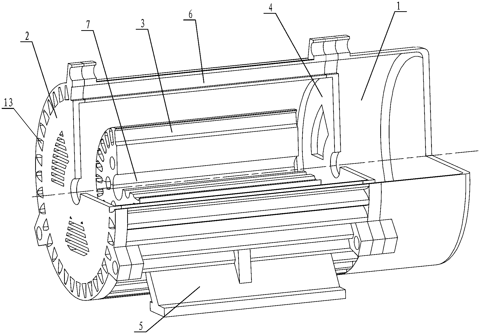
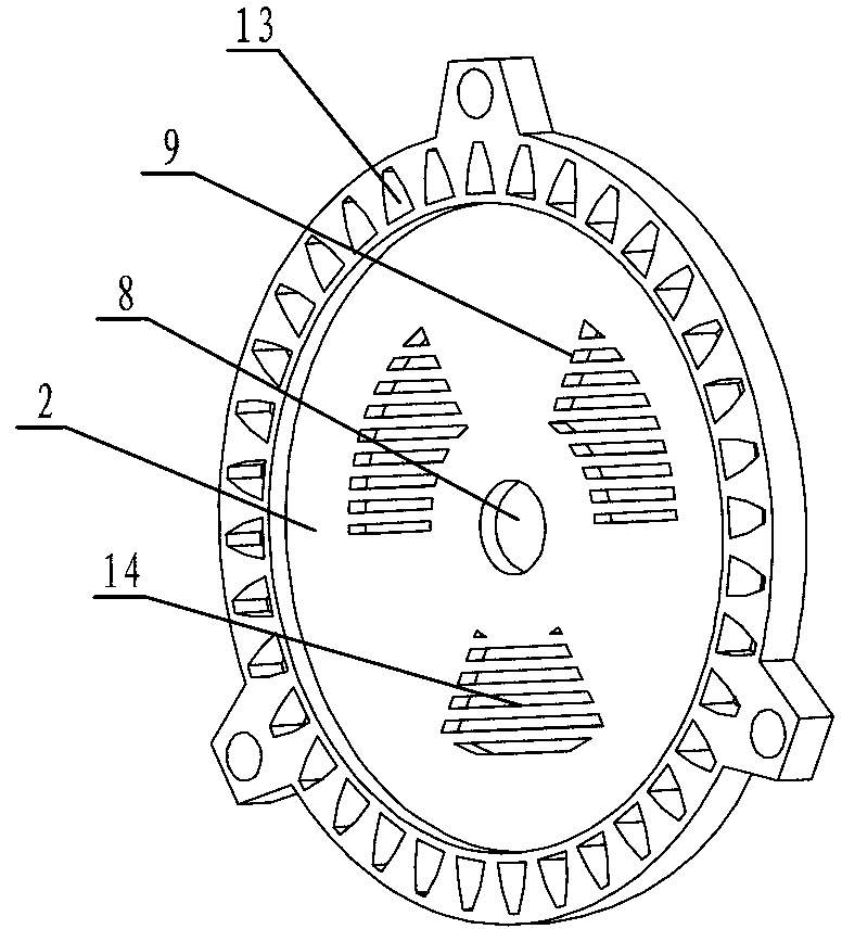
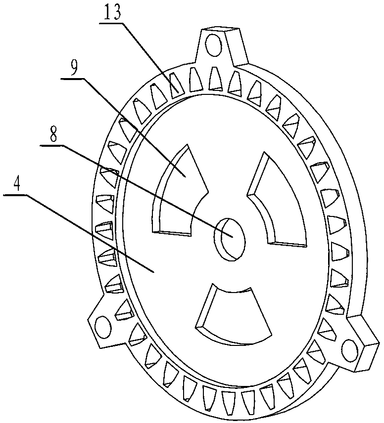
[0028] Such as Figure 1 to Figure 7 As shown, the motor multi-cavity U-shaped cooling system of the present invention includes a motor fan end cover 1, a motor load end cover 2, a rotor core 3, a motor fan end cover 4, a machine base 5, a casing 11 and a heat dissipation wing 6,

[0029] The heat dissipation fins 6 are fixed on the casing 11, the machine base 5 is fixedly installed on the casing 11 and the heat dissipation fins 6, the rotor core 3 is provided with a rotor shaft hole 7, and the rotor core 3 is connected to the motor through the rotor shaft hole 7. The rotating shaft is assembled, the casing 11 is set on the outside of the rotor core 3, the motor load end cover 2 is installed on the left end of the casing 11 and the cooling fin 6, and the motor fan end is installed on the right end of the casing 11 and the cooling fin 6 Cover ...


PUM


Abstract

The invention discloses a multi-inner cavity U-shaped cooling system of a motor, belongs to the technical field of electromechanical, and aims at solving the problems of bad cooling effect of the current sealed motor and unbalanced temperature rise distribution in the motor. Fan-shaped vent holes are formed in an end cover of a motor load end and an end cover of a motor fan end, second axial ventilating ducts are formed in outer flanges of the end cover of the motor load end and the end cover of the motor fan end, a plurality of first axial ventilating ducts are formed in a rotor core along the axial direction, the sections of the first axial ventilating ducts are fan-shaped or circular, radiating fins have hollow vent hole structures, the number of the second axial ventilating ducts is equal to the number of the hollow vent holes, and the second axial ventilating ducts are communicated with the hollow vent holes. The integral cooling capability of the multi-inner cavity U-shaped cooling system disclosed by the invention can be higher than 30%, and the radiating fins are of hollow structures, thereby increasing the internal radiating areas of the radiating fins on the condition of ensuring invariable contact area between the exterior of the machine body and the air region; and the radiating efficiency is 1.5 times as large as the original radiating efficiency under the same air quantity.

Description

technical field [0001] The invention relates to a motor cooling system, in particular to a motor multi-cavity U-shaped cooling system, which belongs to the technical field of motors. Background technique [0002] For small and medium-sized motors that adopt a closed cooling method, the loss in the motor is mainly dissipated to the external environment through the cooling fins of the casing that are in contact with the stator core. However, due to the limited heat dissipation capacity of the motor stator cooling fins, and with the continuous increase of the power density of small and medium-sized motors, the loss of the motor also increases accordingly, resulting in the loss energy in the motor cannot be effectively dissipated to the external space, and the motor's The temperature rise will be greatly increased, exceeding the temperature rise limit of the motor insulation material, resulting in aging of the motor insulation, and seriously affecting the normal operation of th...

Claims


Application Information

Patent Timeline
Patent Type & Authority Applications(China)
IPC IPC(8): H02K9/06H02K5/18H02K5/20H02K1/32
Inventor 丁树业董传友王勇郭保成
Owner HARBIN UNIV OF SCI & TECH
Learn More