Reducing coupling injection mold core-pulling mechanism

A technology for injection molds and core-pulling mechanisms, applied in the field of injection molds for pipe joints with different diameters, can solve problems such as high energy consumption, increased size and volume of molds and injection molding machines, and increased manufacturing costs of molds and injection molding machines

Inactive Publication Date: 2013-09-04
TAIZHOU HUANGYAN WEIDA PLASTIC MACHINERY
View PDF7 Cites 9 Cited by
  • Summary
  • Abstract
  • Description
  • Claims
  • Application Information

AI Technical Summary

Problems solved by technology

When the existing injection molds for manufacturing different-diameter pipe joints are demolded from the buckle on the outer wall, a side core-pulling slider is generally installed on the movable mold side, and an inclined guide column is installed on the fixed mold plate to drive the side core-pulling when the mold is opened. The slider is used for core pulling, or an oil cylinder is installed outside the movable mold, and the piston rod of the oil cylinder is used to drive the side core-pulling slider to pull the core. This type of structure requires a large space, and the size and volume of the mold and the injection molding machine will increase. Large, which increases the manufacturing cost of the mold and injection molding machine, and consumes a lot of energy during processing, takes a long time, and is inconvenient to process, and it is a big problem to demould the buckle on the inner wall

Method used


Image

  • Reducing coupling injection mold core-pulling mechanism
  • Reducing coupling injection mold core-pulling mechanism
  • Reducing coupling injection mold core-pulling mechanism

Examples


Embodiment Construction

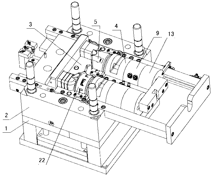
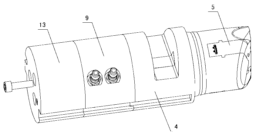
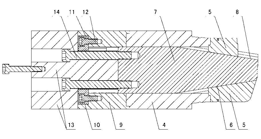
[0013] The invention relates to a core-pulling mechanism for injection molds of pipe joints with different diameters, such as figure 1 — Figure 7 As shown, it includes a movable mold backing plate 1 and a movable template 2, and a movable mold insert 3 is installed on the movable template. 2 and the movable mold insert 3 are equipped with a floating core-pulling mechanism, the secondary internal core-pulling mechanism includes a main core 4, the front end of the main core is connected to the inner core-pulling small slider 5, and the inside of the inner core-pulling small slider is shaped on Inner inclined sliding surface 6, sliding rod 7 is set in the main core, and the outer inclined sliding surface 8 is formed on the sliding rod, the outer inclined sliding surface 8 matches the inner inclined sliding surface 6, and the connecting seat 9 is installed at the rear end of the main core , the rear end of the connecting seat is shaped with a mounting groove 10, a fixing plate 1...


PUM


Abstract

The invention discloses a reducing coupling injection mold core-pulling mechanism which comprises a movable mold base plate and a movable template, wherein a movable mold insert is arranged on the movable template; a secondary internal core-pulling mechanism is arranged on the movable template; floating core-pulling mechanisms are arranged on the movable mold base plate, the movable template and the movable mold insert; according to the secondary internal core-pulling mechanism, an inner inclined sliding surface is formed in a core-pulling small slide block connected in front of a main mold core; an outer inclined sliding surface formed on a sliding rod arranged in the main mold core is matched with the inner inclined sliding surface; a fixing plate is arranged in a mounting groove formed in the rear end of a connecting seat behind the main mold core and is fixed together with the connecting seat through a screw; the sliding seat and the sliding rod are fixed through a bolt; according to the floating core-pulling mechanism, one end of a spring arranged in the movable template is contacted with the movable template, and the other end of the spring is contacted with the movable mold base plate; a core-pulling slide block arranged in the movable mold insert is matched with an external fastener; the core-pulling slide block is provided with a T-shaped clamping block; inclined guide slots formed in an I-shaped locking module are formed in the movable template and the movable mold insert; the upper part of the I-shaped locking module is matched with the T-shaped clamping block through the inclined guide slots; and the lower part of the I-shaped locking module and the movable mold base plate are fixed together.

Description

technical field [0001] The invention relates to an injection mold for pipe joints with different diameters, in particular to a core-pulling mechanism for the injection mold for pipe joints with different diameters. Background technique [0002] The joints of different-diameter pipe fittings play the role of transitional connection to the drain pipe in the drainage pipe fittings. In order to connect the joints of different-diameter pipe fittings with the drain pipe and assemble them reliably, buckles are made on the outer and inner walls of the joints of different-diameter pipe fittings to prevent the pipe fittings from falling off. . When the existing injection molds for manufacturing different-diameter pipe joints are demolded from the buckle on the outer wall, a side core-pulling slider is generally installed on the movable mold side, and an inclined guide column is installed on the fixed mold plate to drive the side core-pulling when the mold is opened. The slider is use...

Claims


Application Information

Patent Timeline
Patent Type & Authority Applications(China)
IPC IPC(8): B29C45/33
Inventor 张欢庆
Owner TAIZHOU HUANGYAN WEIDA PLASTIC MACHINERY
Why Eureka
Try Eureka