Eureka AIR delivers breakthrough ideas for toughest innovation challenges, trusted by R&D personnel around the world.

Self-excitation type pulse polycrystalline diamond compact (PDC) drill bit

A self-excited drill bit technology, which is applied in the direction of drill bits, drilling equipment, earthwork drilling, etc., can solve the problems of short service life, excessive crushing, and low water efficiency of the drill bit, and achieve the purpose of increasing hydraulic rock breaking capacity and avoiding excessive crushing Effect

Active Publication Date: 2013-09-04
TIANJIN BANGPU PETROLEUM TECH EQUIP
View PDF8 Cites 6 Cited by
  • Summary
  • Abstract
  • Description
  • Claims
  • Application Information

AI Technical Summary

Problems solved by technology

[0002] At present, ordinary jet PDC drill bits are widely used to flush the bottom of the well with constant water pressure. The disadvantages are low water efficiency, less footage, slow speed, excessive fragmentation, and short service life of the drill bit.

Method used


Image

  • Self-excitation type pulse polycrystalline diamond compact (PDC) drill bit
  • Self-excitation type pulse polycrystalline diamond compact (PDC) drill bit

Examples


Embodiment 1

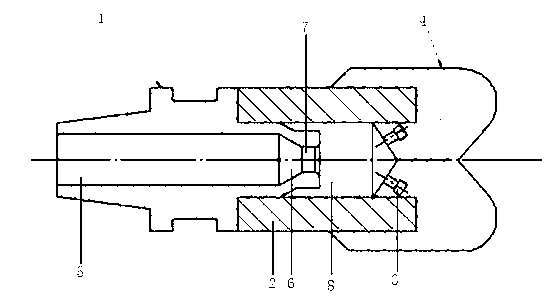
[0011] Embodiment one: in figure 1 Among them, this self-excited pulse PDC drill bit includes the upper drill bit upper body 1, the drill bit upper body 1 is connected to the drill bit body 2 through threads, the inner nozzle 7 is installed inside the drill bit body 2, and the drill bit blade is fixed outside the drill bit body 2 4. The drill bit blade 4 is inlaid with a diamond composite sheet. There is a central hole 5 on the axis of the upper body 1 of the drill bit. The diameter of the central hole 5 is 70 mm; The inner nozzle 7, the lower end of the inner nozzle 7 is the self-excited pulse cavity 8 in the drill body, the lower part of the self-excited pulse cavity 8 is cylindrical, the upper part of the self-excited pulse cavity 8 is a basin-shaped inner slope, and the self-excited pulse cavity 8 The lower part communicates with 4 nozzles 3 .

[0012] The diameter of the inner nozzle 7 is 0.5 times the diameter of the central hole 5, the diameter of the self-excited puls...

Embodiment 2

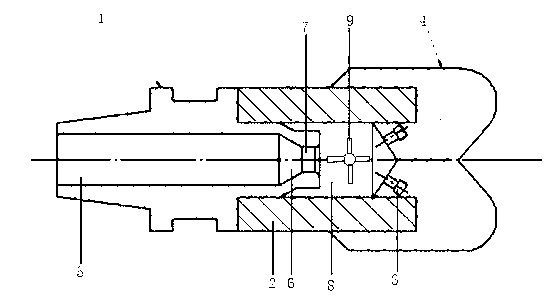
[0013] Embodiment two: in figure 2 Among them, a runner 9 is also installed in the self-excited pulse cavity at the lower part of the inner nozzle inside the drill body. There are 4 blades on the runner. The axis of the horizontal runner and the axis of the vertical center hole do not intersect. The distance is 1 / 10 of the diameter of the center hole. Due to the high-speed rotation of the runner 9, the pressure of the water flow in the self-excited pulse chamber 8 changes at high frequency, so that the impact effect of the water flow is greatly improved.

[0014]


PUM


Abstract

A self-excitation type pulse polycrystalline diamond compact (PDC) drill bit comprises a drill bit upper body at the upper portion, wherein an inner spray nozzle is installed inside a drill bit body, a drill bit blade is fixed outside the drill bit body, a diamond compact is inlayed on the drill bit blade, a central hole is formed on the axis of the drill bit upper body, and the diameter of the central hole is 55-80mm. A contracting taper hole is formed at the lower end of the central hole, the inner spray nozzle is arranged at the lower end of the contracting taper hole, the lower end of the inner spray nozzle is a self-excitation pulse cavity in the drill bit body, and the lower portion of the self-excitation pulse cavity is communicated with 4-6 spray nozzles. A rotating wheel can be further installed in the self-excitation pulse cavity at the lower portion of the inner spray nozzle inside the drill bit body, and liquid in a drill rod forms self-excitation pulse in the self-excitation pulse cavity and then is sprayed out through the spray nozzles at the lower portion to produce pulse oscillation, so that water pressure at the bottom of the drill bit is varying, the hydraulic rock breaking capacity of the drill bit at the bottom of a well is improved, meanwhile excessive breaking of rocks at the bottom of the well is also avoided, and the impact effect is more than two times of the effect of common steady pressure jet flows.

Description

technical field [0001] The present invention relates to a drilling tool in the drilling process of oil wells, that is, a self-excited pulse PDC drill bit, which converts the ordinary jet flow output by the drilling fluid pump into a self-excited pulse jet flow, and amplifies the jet flow to obtain The output in the form of pulse oscillation doubles the hydraulic rock breaking capacity of the bottom hole drill bit. High efficiency transmission of drilling fluid energy is realized. Background technique [0002] At present, ordinary jet PDC drill bits are widely used to flush the bottom of the well with constant water pressure. The disadvantages are low water efficiency, less footage, slow speed, excessive fragmentation, and short service life of the drill bit. Contents of the invention [0003] In order to overcome the above-mentioned shortcomings of constant water pressure for flushing the bottom of the well, the present invention applies the principle of self-excited puls...

Claims


Application Information

Patent Timeline
Patent Type & Authority Applications(China)
IPC IPC(8): E21B10/38
Inventor 刘勤赵静华
Owner TIANJIN BANGPU PETROLEUM TECH EQUIP
Why Eureka
Eureka Blog
Learn More