
Low-pressure anti-seepage device of gearbox

A kind of gearbox, anti-leakage technology, applied in the direction of transmission parts, belt/chain/gear, mechanical equipment, etc., can solve the problems of environmental equipment pollution, force and deformation of the sub-box surface, bearing heating, etc., so as not to pollute the environment , to achieve automatic control, improve the effect of temperature rise

Active Publication Date: 2013-09-04
TAIZHONG TIANJIN BINHAI HEAVY MACHINERY
View PDF6 Cites 3 Cited by
  • Summary
  • Abstract
  • Description
  • Claims
  • Application Information

AI Technical Summary

Problems solved by technology

[0003] 1. The combination of the sub-box surface of the box body is not strict. During use, due to the action of alternating load and the influence of vibration, the sub-box surface is deformed by force and creates a gap, and the lubricating medium leaks from the gap.
[0004] 2. Oil leakage of input and output shafts
[0005] 3. The input pressure of the transmission system with thin oil forced lubrication is too large, which increases the leakage of lubricating medium from the gap
Severe leakage of the lubricating medium will cause the gearbox to lack oil and cut off oil, which will intensify the wear of the tooth surfaces of the gears that are meshing with each other, making the high-speed and heavy-load rotating bearings heat up, and then pitting, gluing, and peeling of the gear tooth surfaces will occur. The bearing on the gear shaft is locked, causing an accident in the equipment
And the leaking lubricating medium seriously pollutes the surrounding environment and equipment

Method used


Image

  • Low-pressure anti-seepage device of gearbox
  • Low-pressure anti-seepage device of gearbox
  • Low-pressure anti-seepage device of gearbox

Examples


Embodiment Construction

[0023] The present invention will be further described below in conjunction with the accompanying drawings.

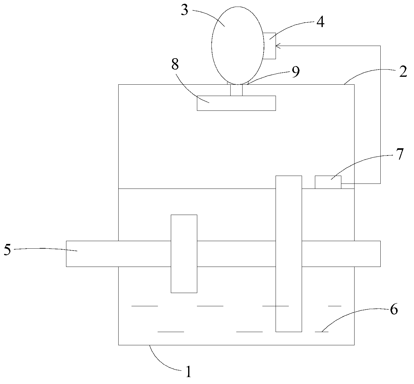
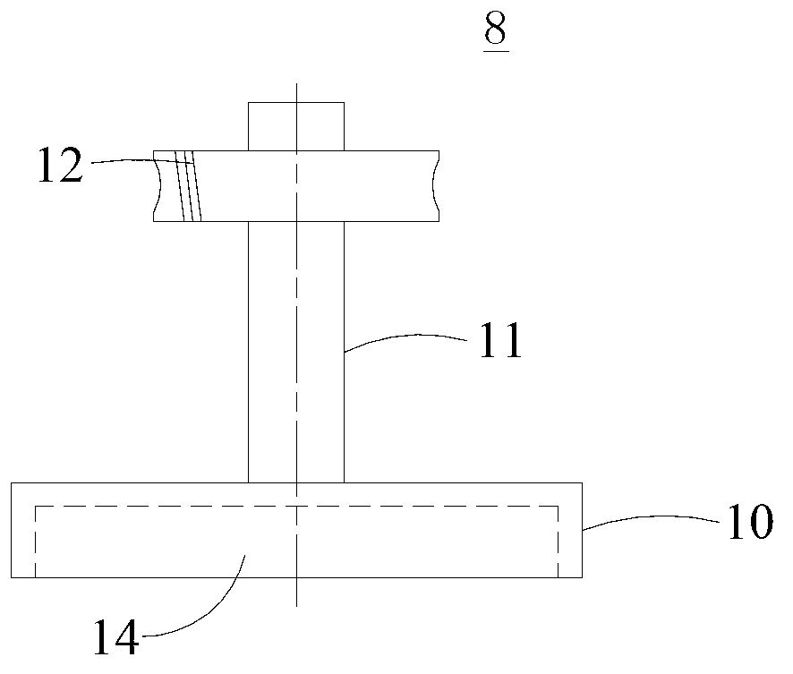
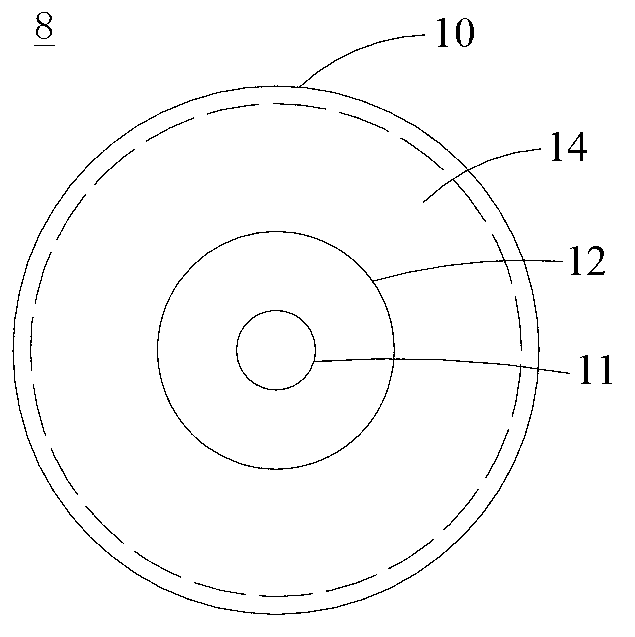
[0024] Such as figure 1 As shown, the gearbox low-pressure anti-leakage device of the present invention includes: a gearbox housing 1, a transmission shaft system 5 arranged in the housing 1, and a lubricating medium 6 accommodated in the housing 1 for lubricating the transmission shaft system 5 The vacuum pump 3 and the control system 4 arranged on the casing 1 are located on the inner wall of the casing 1 for detecting the pressure sensor 7 of the air pressure in the casing 1, and are arranged near the exhaust hole 9 of the top plate 2 of the casing 1 Rotating disc 8 of porous material.

[0025] The vacuum pump 3 can be fixed on the outer wall surface of the top plate 2 of the gearbox housing 1 by welding or screwing. When the gearbox is running, when the pressure in the gearbox casing 1 is greater than the upper limit of the working pressure of the vacuum pump p ...


PUM


Abstract

The invention provides a low-pressure anti-seepage device of a gearbox. The low-pressure anti-seepage device comprises a gearbox casing, a transmission shaft system arranged in the casing, lubricating media contained in the casing and used for lubricating the transmission shaft system, a vacuum pump and a control system which are arranged above the casing, a pressure sensor located on the inner wall of the casing and used for detecting pressure in the casing and a porous material rotating disk arranged on the surface of the inner wall of the casing and used for adsorbing the lubricating media. The vacuum pump is arranged on the casing so that pressure in the casing can constantly keep being lower than pressure of the external environment. The porous material rotating disk is arranged at the position corresponding to an air exhaust of the vacuum pump so that the lubricating media can be prevented from being sucked into the external environment. Automatic control on starting and stopping of the vacuum pump can be achieved through the pressure sensor and the control system. Therefore, the low-pressure anti-seepage device has the advantages of being free of oil seepage, not polluting the environment and being capable of achieving automatic control.

Description

technical field [0001] The invention relates to an anti-leakage device for transmission equipment, in particular to a low-pressure anti-leakage device for a gearbox. Background technique [0002] The gearbox is the main transmission equipment widely used in industrial enterprises. As the core of the transmission part, its normal and stable operation is an important guarantee for the efficient operation of the main equipment. During the long-term operation of the gearbox, due to factors such as manufacturing, vibration, wear, pressure, temperature, and disassembly and maintenance, there will be varying degrees of lubrication medium leakage. The main reasons for the leakage of lubricating medium are as follows: [0003] 1. The split surface of the box body is not tightly combined. During use, due to the action of alternating loads and the influence of vibration, the split surface is deformed by force and creates a gap, and the lubricating medium leaks from the gap. [0004] ...

Claims


Application Information

Patent Timeline
Patent Type & Authority Applications(China)
IPC IPC(8): F16H57/029
Inventor 臧日兴张敏张林威王晓凌
Owner TAIZHONG TIANJIN BINHAI HEAVY MACHINERY
Learn More