Solar wing hinge line drive characteristic test device

A technology for driving characteristics and testing devices, which is used in measurement devices, testing of mechanical components, testing of machine/structural components, etc., to achieve the effect of improving reliability and development level

Inactive Publication Date: 2015-09-16
LANZHOU INST OF PHYSICS CHINESE ACADEMY OF SPACE TECH
View PDF6 Cites 2 Cited by
  • Summary
  • Abstract
  • Description
  • Claims
  • Application Information

AI Technical Summary

Problems solved by technology

The solar wing hinge line driving characteristic test device can realize the installation of hinges, cables and other tested parts, and at the same time realize specific tension loading. The test device simulates the process of solar wing deployment and retraction, and tests the rotation angle and torque parameters in real time to obtain accurate and reliable results. Test data such as driving torque, frictional resistance torque and stiffness can improve the reliability and development level of space application equipment. At present, there is no dedicated testing device for the driving characteristics of the solar wing hinge line

Method used


Image

  • Solar wing hinge line drive characteristic test device
  • Solar wing hinge line drive characteristic test device
  • Solar wing hinge line drive characteristic test device

Examples


Embodiment 1

[0020] Simulation test of inter-board hinge cables

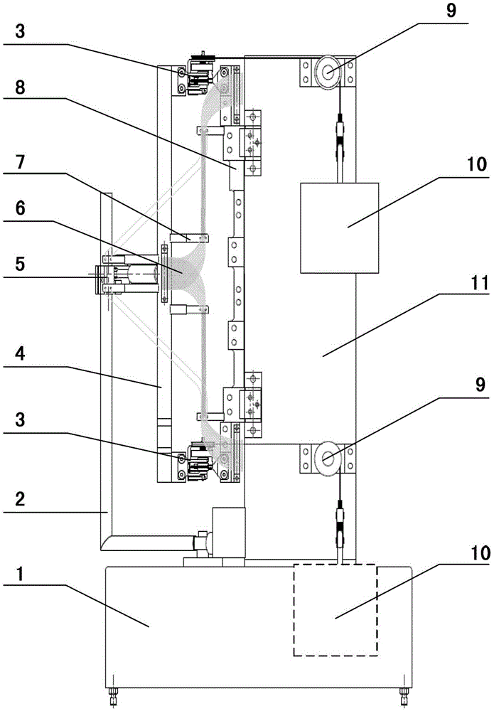
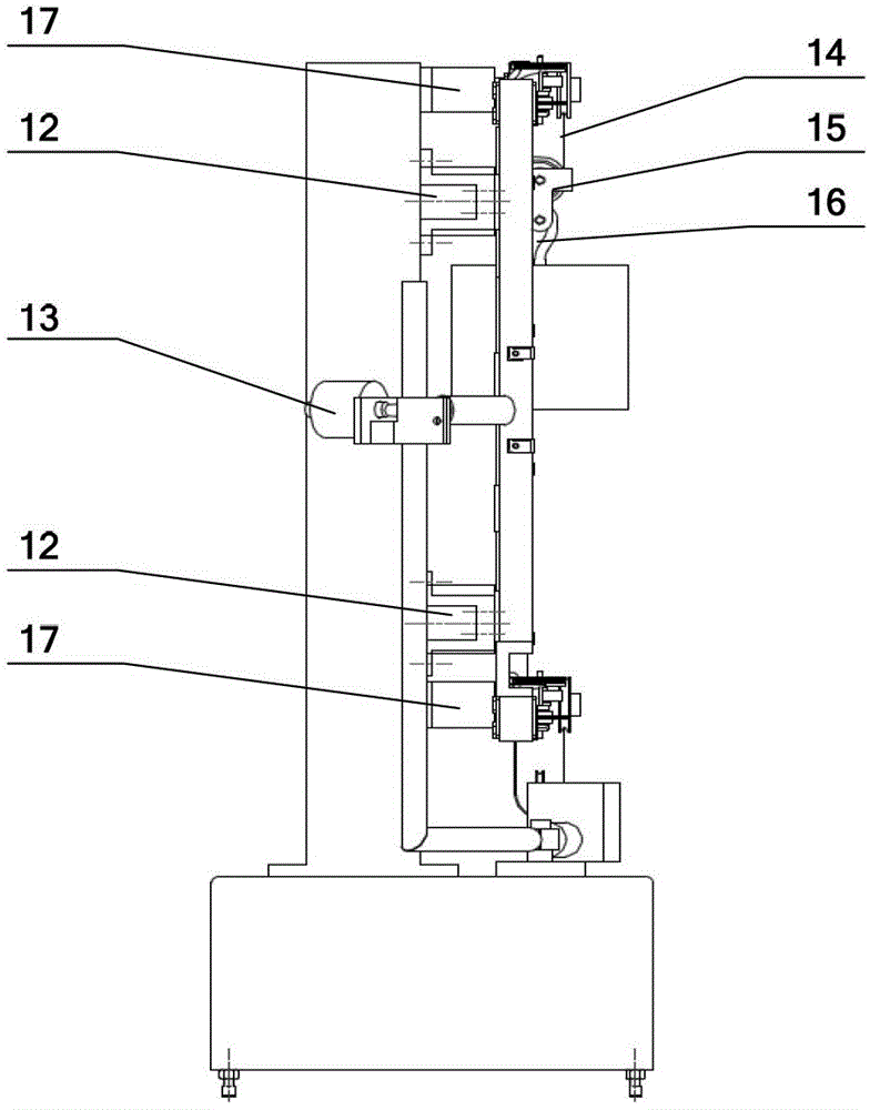
[0021] The inter-board test hinge 3 is installed on the fixed bracket 8 and the rotating bracket a4, the inter-board test cable 6 is fixed on the cable fixing seat 7, the main shaft 24 is rotated, and the sensor lever 18 presses the force measuring head of the load cell 13 to generate The pressure signal is sent to the signal processing circuit through the signal line of the load cell 13; the tension of the locking ring is applied, the pulley bracket a17 is installed on the column assembly 11, the double pulley assembly 9 is installed on the pulley bracket a17, and the steel wire rope 14 passes through the hinge roller between the plates The groove is connected with the movable pulley assembly 15, and the upper and lower hinges are installed respectively. When tension is applied, the upper and lower hooks 16 load the same weight 10, such as figure 1 As shown, the main shaft 24 is rotated to realize the simulation test of the...

Embodiment 2

[0023] Root hinge cable simulation

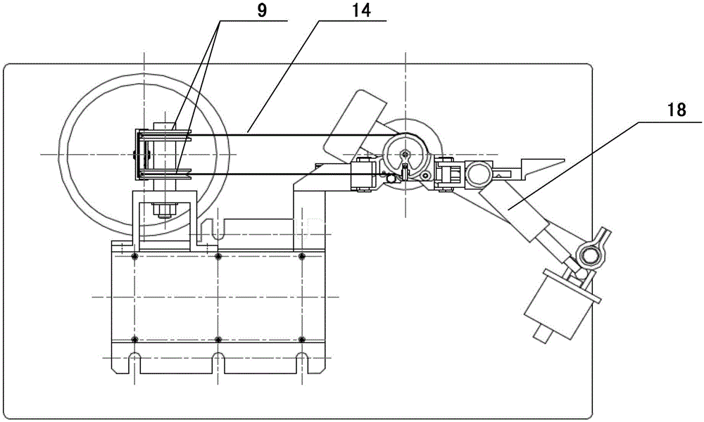
[0024] The root test hinge 22 is installed on the fixed bracket 8 and the rotating bracket b25, the root test cable 23 is fixed on the cable clamp 21, the main shaft 24 is rotated, the sensor lever 18 presses the force measuring head of the load cell 13 to generate a pressure signal, Give the signal processing circuit through the signal line of the load cell 13; apply the locking ring tension, the pulley bracket b20 is installed on the column assembly 11, the double pulley assembly 9 is installed on the pulley bracket b20, the steel wire rope 14 passes through the root hinge roller groove, and The movable pulley assembly 15 is connected, and when the tension is applied, the hook 16 loads the weight 10, such as Figure 4 As shown, the main shaft 24 is rotated to realize the simulation test of the root hinge cable under the tension condition of the locking ring.


PUM


Abstract

The invention discloses a driving property test device for a hinge line of a solar wing. The device comprises a base, a shift rod, a rotary bracket a, a sensor seat, a cable fixing seat, a fixed bracket, a double-pulley assembly, a loading heavy block, a vertical column assembly, a fixed seat, a force measuring sensor, a steel wire rope and a movable pulley assembly, wherein the interior of the base is provided with a worm and gear speed reducer, the vertical column assembly is vertically and fixedly arranged at the top of the base, and the double-pulley assembly is fixedly arranged on the vertical column assembly. The test device has the advantages that the unfolding and folding processes of the solar wing can be simulated; the rotation angle and the torque parameter can be tested in real time, and the accurate and reliable test data, such as driving torque, friction drag torque and rigidity, can be obtained; and the reliability and the development level of space application equipment are improved.

Description

technical field [0001] The invention relates to a test device for driving characteristics of a solar wing hinge line, which belongs to the technical field of space application equipment. Background technique [0002] In order to ensure the reliable deployment of the solar wing on orbit and limit the impact load at the end of deployment within an acceptable range, it is necessary to control its driving torque margin. The calculation of the moment margin needs to use parameters such as the driving moment of the hinge (inter-plate hinge and root hinge), the resistance moment of the connecting cable, and the frictional resistance moment caused by the hinge line such as the tension of the locking ring. The solar wing hinge line driving characteristic test device can realize the installation of hinges, cables and other tested parts, and at the same time realize specific tension loading. The test device simulates the process of solar wing deployment and retraction, and tests the ro...

Claims


Application Information

Patent Timeline
Patent Type & Authority Patents(China)
IPC IPC(8): G01M13/00
Inventor 翟少雄吴跃民李忠梅濮海玲周晖王举王长胜谭立王保成
Owner LANZHOU INST OF PHYSICS CHINESE ACADEMY OF SPACE TECH
Why Eureka
Try Eureka