Spring fatigue testing machine

A technology of fatigue testing and spring sleeve, which is applied in the direction of applying repeated force/pulsation force to test the strength of materials, etc., to achieve the effect of convenient use, reasonable design and accurate test

Inactive Publication Date: 2013-09-04
SHANGDONG ZHONGBAOKANG MEDICAL DEVICES
View PDF9 Cites 3 Cited by
  • Summary
  • Abstract
  • Description
  • Claims
  • Application Information

AI Technical Summary

Problems solved by technology

It can be seen from the analysis that the actual use conditions of the excitation spring are much harsher than those of the spring testing machine, and the existing spring fatigue testing machine cannot meet our use requirements

Method used


Image

  • Spring fatigue testing machine
  • Spring fatigue testing machine
  • Spring fatigue testing machine

Examples


Embodiment Construction

[0016] Embodiments of the present invention are further described below in conjunction with accompanying drawings:

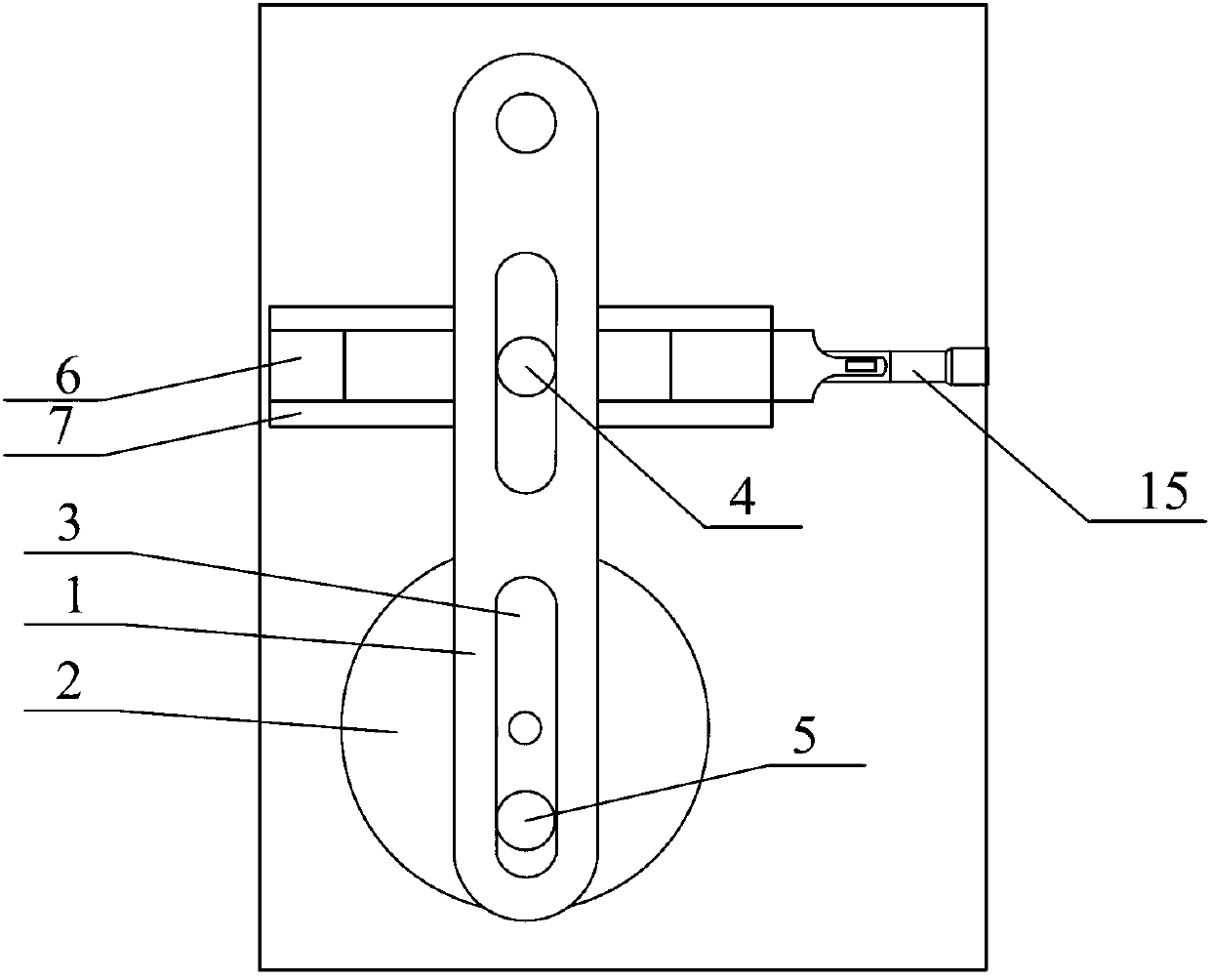
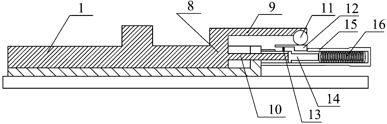
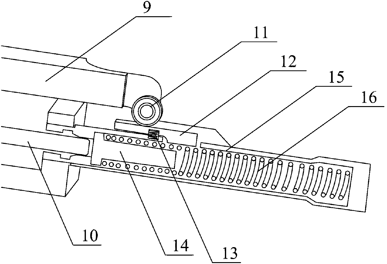
[0017] Such as figure 1 The swing connecting rod in the shown spring fatigue testing machine includes a swing rod 1 and a cam 2. The two ends of the swing rod 1 are provided with a long slot 3, and the cam protrusion 5 on the cam 2 is inserted into the side of the swing rod 1. Through slot 3, the slide rail protrusion 4 is inserted into the through slot 3 on the other side of the swing rod 1, and the cam protrusion 5 and the slide rail protrusion 4 match the width of the through slot 3 of the swing rod 1 to prevent errors in the power transmission process and make the cam 2 The rotation can be accurately transmitted to the slide rail 6. Slide rail 6 slides in chute 7. The end of the slide rail 6 is an F-shaped end 8, the tail of the upper horizontal side 9 of the F-shaped end 8 is provided with a compression bearing 11, the lower horizontal side 10 of the F-sh...


PUM


Abstract

The invention relates to a spring fatigue testing machine used for simulating actual spring fatigue tests. The spring fatigue testing machine is characterized by comprising a swing connecting rod, wherein the swing connecting rod is connected with a slide rail in a cross shape, the tail end of the slide rail is connected with a spring compression mechanism, and the spring compression mechanism is arranged in a spring sleeve. The spring fatigue testing machine provided by the invention is reasonable in design and convenient to use, a smart structure combination is used for performing compression test on the spring, accurately simulating the application environment of the spring and ensuring more accurate spring test.

Description

technical field [0001] The patent of the present invention relates to a spring fatigue testing machine for simulating the actual fatigue testing of springs. Background technique [0002] One of the core components of the syringe is a high-strength compression spring. The method of using the spring is to first compress to a certain length and have a certain potential energy, and then the spring is suddenly activated by the control mechanism to push the push rod of the syringe forward to complete the injection action. The current spring fatigue testing machine uses the cam to compress the spring to make the spring reciprocate. The disadvantages of the prior art are: [0003] 1. The rotation of the cam drives the spring to reciprocate, which cannot truly simulate the compression and excitation of the excitation spring, and it is easy to misjudge the service life of the spring (technical requirements for the excitation spring: the number of times the excitation spring in the ej...

Claims


Application Information

Patent Timeline
Patent Type & Authority Applications(China)
IPC IPC(8): G01N3/34
Inventor 董国明宋奎良路志浩李欣丁金栋胡庆浩
Owner SHANGDONG ZHONGBAOKANG MEDICAL DEVICES
Why Eureka
Try Eureka