Rotation speed measuring mechanism for stabilized platform in dynamic directional rotary guiding drilling tool
A technology of rotary steerable drilling and stable platforms, which is applied in the field of oil and gas drilling, can solve the problems of low measurement accuracy, complex structure of measurement tools, cumbersome signal processing, etc., and achieve the effects of precise control, compact structure and convenient debugging
- Summary
- Abstract
- Description
- Claims
- Application Information
AI Technical Summary
Problems solved by technology
Method used
Image


Examples
Embodiment 1
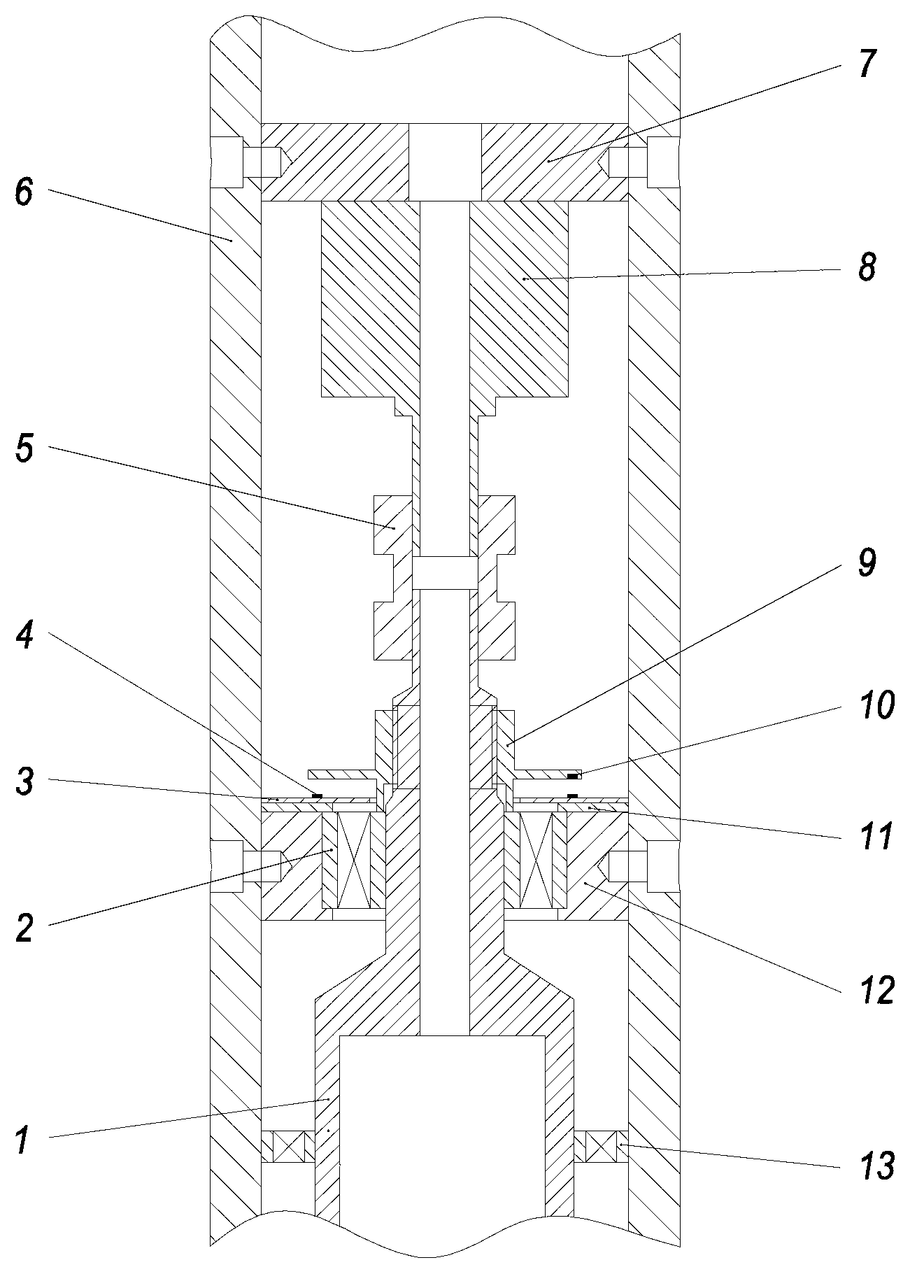
[0026] Example 1: as figure 1 As shown, a rotational speed measuring mechanism for a stable platform in a dynamic pointing rotary steerable drilling tool includes a rotating outer cylinder 6 and a stable platform platform body 1 sheathed in the rotating outer cylinder 6, and the inner side of the rotating outer cylinder 6 is connected with a motor to install Plate 7, a motor 8 is installed in the central part of the motor mounting plate 7, and the lower end of the motor 8 is transitionally matched with the stable platform table body 1 through the coupling 5 to drive the stable platform table body 1 to rotate; the upper end of the stable platform table body 1 is installed by The bearing sleeve 12 inside the rotating outer cylinder 6 and the double row angular contact ball bearing 2 embedded in the bearing sleeve 12 are connected to the rotating outer cylinder 6, and the outer side of the upper end of the stable platform body 1 is sleeved with a tightening nut 9, The middle of t...
Embodiment 2
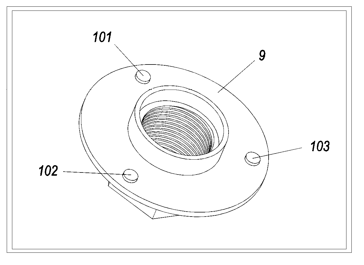
[0042] Embodiment 2: Different from Embodiment 1, in Embodiment 2, three magnetic steels are embedded in the lower side of the protruding circular plate in the middle of the fastening nut 9; The interval angle distribution of the Hall sensor circuit board 3 is provided with a microcontroller 15, an AND gate 14 and six groups of Hall element circuits containing the Hall sensor 4, and the Hall sensors 4 in the six groups of Hall element circuits are evenly distributed in the On the Hall sensor circuit board 3 , each group of Hall element circuits is connected to the single-chip microcomputer 15 through the AND gate 14 .
Embodiment 3
[0043] Embodiment 3: Different from Embodiment 1, in Embodiment 3, four magnetic steels are embedded in the lower side of the protruding circular plate in the middle of the fastening nut 9; The interval angle distribution of the Hall sensor circuit board 3 is provided with a single-chip microcomputer 15, an AND gate 14 and six groups of Hall element circuits containing the Hall sensor 4, and the Hall sensors 4 in the six groups of Hall element circuits are evenly distributed On the Hall sensor circuit board 3, each group of Hall element circuits is connected to the microcontroller through an AND gate.
PUM
 Abstract
Description
Claims
Application Information
 - R&D
- Intellectual Property
- Life Sciences
- Materials
- Tech Scout
- Unparalleled Data Quality
- Higher Quality Content
- 60% Fewer Hallucinations
Browse by: Latest US Patents, China's latest patents, Technical Efficacy Thesaurus, Application Domain, Technology Topic, Popular Technical Reports.
© 2025 PatSnap. All rights reserved.Legal|Privacy policy|Modern Slavery Act Transparency Statement|Sitemap|About US| Contact US: help@patsnap.com