
Mechanism for Measuring the Rotational Speed ​​of Stable Platform in Dynamic Pointing Rotary Steerable Drilling Tool

A rotary steerable drilling and stable platform technology, applied in the field of oil and gas drilling, can solve the problems of cumbersome signal processing, low measurement accuracy, and complex structure of measurement tools, and achieve the effects of compact structure, precise control, and convenient debugging

Inactive Publication Date: 2015-08-05
CHINA UNIV OF PETROLEUM (EAST CHINA)
View PDF4 Cites 0 Cited by
  • Summary
  • Abstract
  • Description
  • Claims
  • Application Information

AI Technical Summary

Problems solved by technology

[0006] The present invention aims at the above-mentioned deficiencies such as low measurement accuracy, complex structure of measuring tools and cumbersome signal processing when measuring the rotating speed of the stable platform in the existing oil and gas drilling process, and provides a dynamic pointing rotary steering drilling tool for stabilizing the platform. The rotational speed measuring mechanism, the said rotational speed measuring mechanism is simple in structure and reasonable in design, and can provide high-precision real-time rotational speed measurement data for the precise control of the stable platform's geographic static state, ensuring the effective control of the guiding well deviation and azimuth angle during the drilling process

Method used


Image

  • Mechanism for Measuring the Rotational Speed ​​of Stable Platform in Dynamic Pointing Rotary Steerable Drilling Tool
  • Mechanism for Measuring the Rotational Speed ​​of Stable Platform in Dynamic Pointing Rotary Steerable Drilling Tool
  • Mechanism for Measuring the Rotational Speed ​​of Stable Platform in Dynamic Pointing Rotary Steerable Drilling Tool

Examples


Embodiment 1

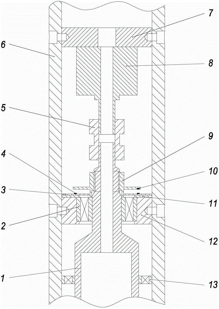
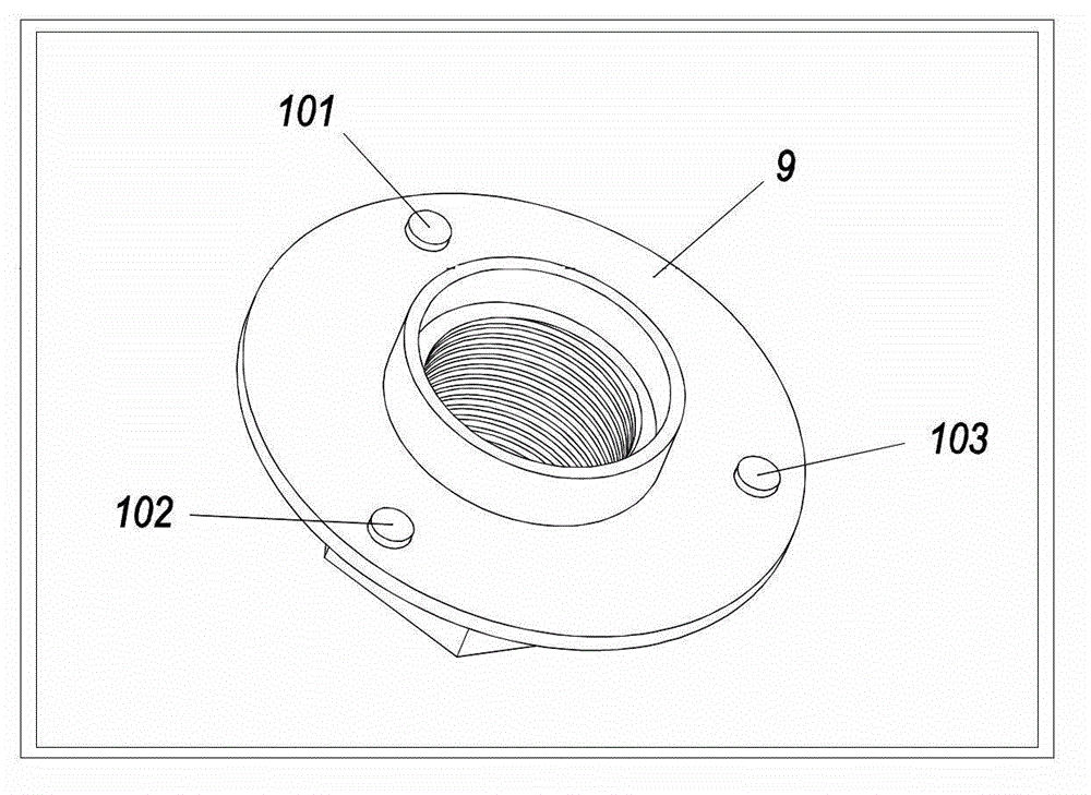
[0026] Embodiment 1: as figure 1 As shown, a rotational speed measurement mechanism of a stable platform in a dynamic pointing rotary steerable drilling tool includes a rotating outer cylinder 6 and a stable platform body 1 set in the rotating outer cylinder 6, and the inner side of the rotating outer cylinder 6 is connected with a motor installation Plate 7, a motor 8 is installed in the center of the motor mounting plate 7, the lower end of the motor 8 is transitionally matched with the stable platform body 1 through the coupling 5, and drives the stable platform body 1 to rotate; the upper end of the stable platform body 1 is installed The bearing sleeve 12 inside the rotating outer cylinder 6 and the double-row angular contact ball bearing 2 embedded in the bearing sleeve 12 are connected with the rotating outer cylinder 6, and the outer side of the upper end of the stable platform body 1 is sleeved with a fastening nut 9, The middle part of the fastening nut 9 is provided...

Embodiment 2

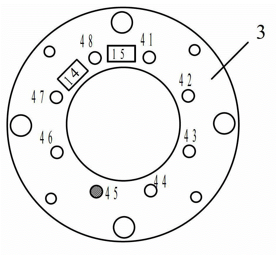
[0042] Embodiment 2: Different from Embodiment 1, in Embodiment 2, three magnetic steels are embedded in the lower side of the protruding circular plate in the middle of the fastening nut 9; The interval angle distribution; the Hall sensor circuit board 3 is provided with a single-chip microcomputer 15, an AND gate 14 and six groups of Hall element circuits containing the Hall sensor 4, and the Hall sensors 4 in the six groups of Hall element circuits are evenly distributed on the On the Hall sensor circuit board 3 , each group of Hall element circuits is connected to the single-chip microcomputer 15 through the AND gate 14 .

Embodiment 3

[0043] Embodiment 3: Different from Embodiment 1, in Embodiment 3, four magnetic steels are embedded in the lower side of the protruding circular plate in the middle of the fastening nut 9; The interval angle distribution; the Hall sensor circuit board 3 is provided with a single chip microcomputer 15, an AND gate 14 and six groups of Hall element circuits containing the Hall sensor 4, and the Hall sensors 4 in the six groups of Hall element circuits are evenly distributed On the Hall sensor circuit board 3 , each group of Hall element circuits is connected to the single-chip microcomputer through an AND gate.


PUM


Abstract

The invention relates a rotation speed measuring mechanism for a stabilized platform in a dynamic directional rotary guiding drilling tool. The rotation speed measuring mechanism comprises a rotary outer barrel and a stabilized platform body, wherein a motor is arranged on the rotary outer barrel. The measuring mechanism further comprises at least one piece of magnetic steel and at least one group of hall element circuits containing hall sensors, wherein the magnetic steel and the hall sensors are respectively and rigidly connected with the rotary outer barrel and the stabilized platform body. Furthermore, the distance between each piece of magnetic steel and the center of each hall sensor is identical with the distance between each piece of magnetic steel and the center of a rotating shaft of the motor. According to the interaction between the magnetic steel and the hall sensors on a hall sensor circuit board, the rotation speed of the stabilized platform relative to the rotary outer barrel can be measured through circuit processing and algorithm analysis on hall pulse signals. Thus, high-accuracy real-time rotation speed measurement data can be provided for accurate control of a geographical stationary state of the stabilized platform, and effective regulation of guiding well deviation and effective regulation of orientation angles can be guaranteed in a drilling process.

Description

technical field [0001] The invention relates to the technical field of oil and gas drilling, in particular to a rotational speed measuring mechanism of a stable platform in a dynamic pointing rotary steerable drilling tool. Background technique [0002] Changes in the requirements of drilling methods have prompted continuous improvement of drilling tools. With the continuous improvement of drilling technology, various downhole steering tools have appeared one after another. Dynamic pointing rotary steerable drilling technology is a cutting-edge closed-loop automatic drilling technology developed in recent years, which has huge market application potential and scientific research value. Since the downhole drilling tool works in a fully rotating state, it is beneficial to reduce sliding friction and torque, improve displacement extension capability and wellbore purification effect, drill a smooth and regular wellbore, better control well deviation and azimuth, and reduce dogl...

Claims


Application Information

Patent Timeline
Patent Type & Authority Patents(China)
IPC IPC(8): G01P3/44
Inventor 鄢志丹耿艳峰王伟亮王子方杨锦舟吴仲华
Owner CHINA UNIV OF PETROLEUM (EAST CHINA)
Learn More