Storage battery charging device

A charging device and storage battery technology, applied in the direction of battery circuit devices, circuit devices, circuits, etc., can solve the problems of easy failure, inconvenient use of charging clips, etc., to save maintenance costs, ensure charging quality, and avoid poor charging and discharging contacts Effect

Inactive Publication Date: 2013-09-04
唐春正 +1
View PDF6 Cites 0 Cited by
  • Summary
  • Abstract
  • Description
  • Claims
  • Application Information

AI Technical Summary

Problems solved by technology

[0006] The present invention aims at the problems of inconvenient use and prone to failure of the charging clip used in the charging process of the existing storage battery, and provides a storage battery charging device to overcome the above problems

Method used


Image

  • Storage battery charging device
  • Storage battery charging device
  • Storage battery charging device

Examples


Embodiment 1

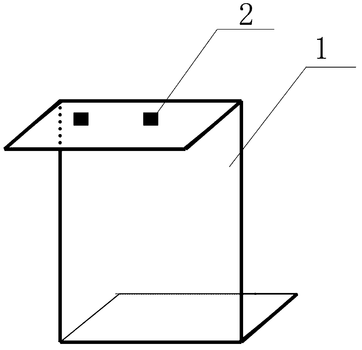
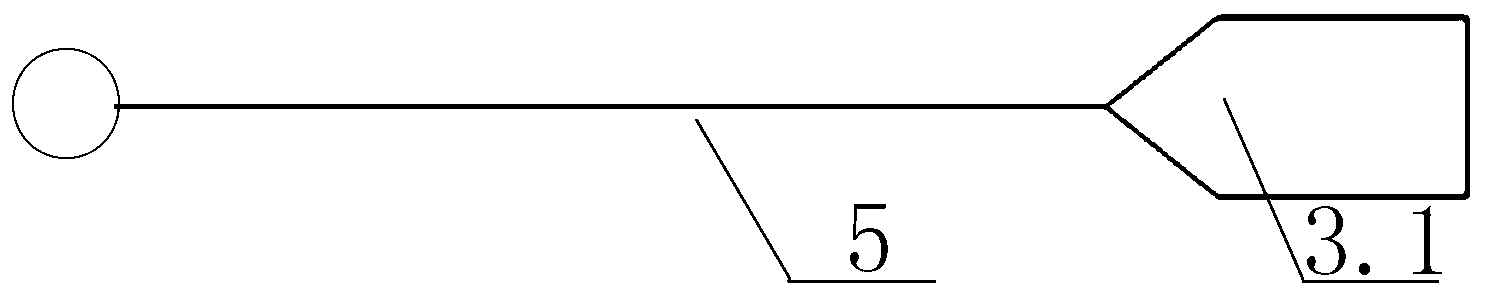
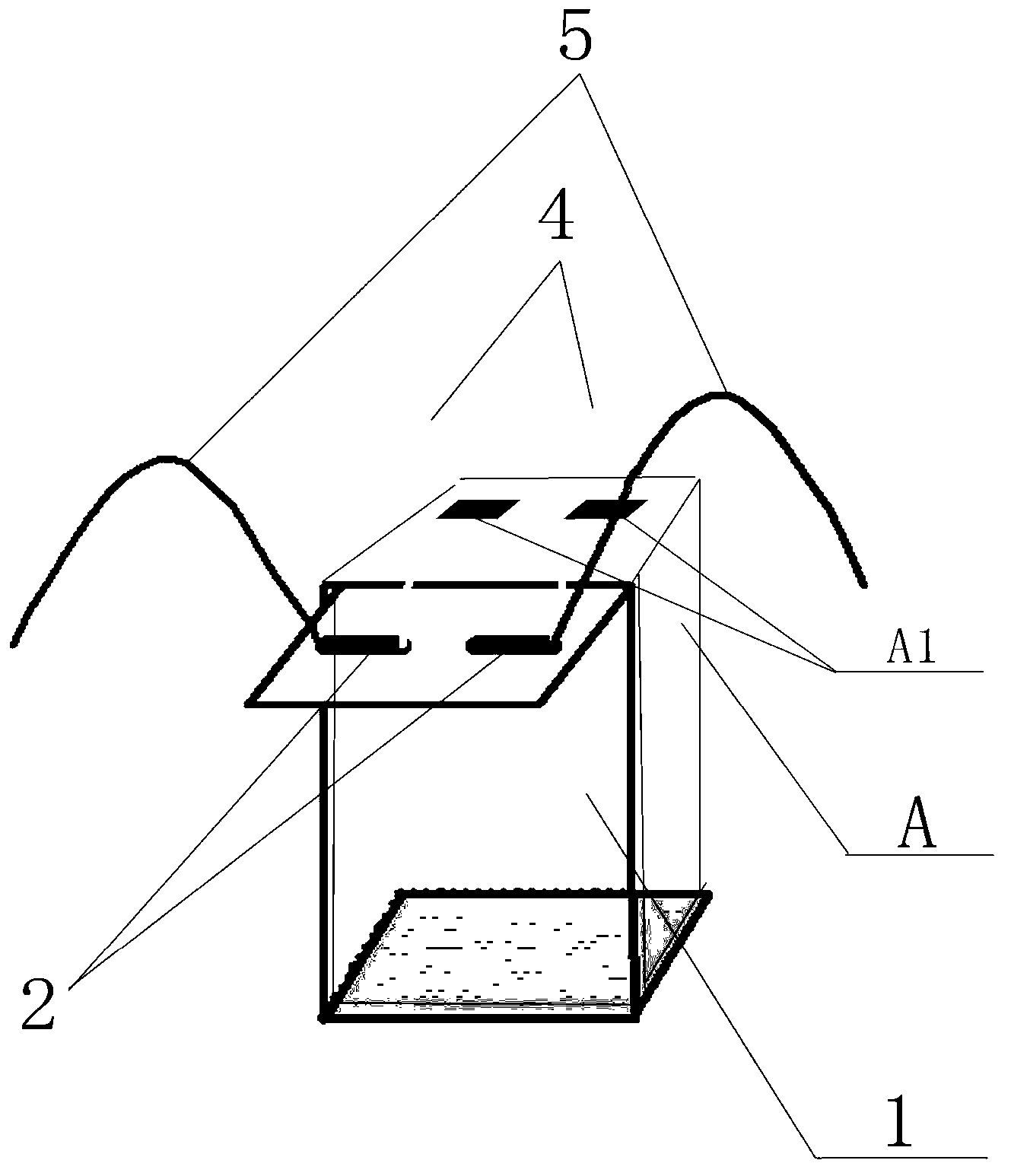
[0039] Such as Figure 1-4 As shown, the battery charging device includes a charging plate 1, which is Z-shaped, and two permanent magnets 2 corresponding to the positive and negative poles A1 of the battery are arranged on the top of the charging plate 1, and the battery A is set and pressed on The protruding surface of the bottom of the charging board 1 presses the charging board 1 tightly, and the two permanent magnets 2 are connected to the positive and negative poles A1 of the battery through the battery connecting wire 4 . In this embodiment, the connecting clip of the battery connecting wire 4 is a connecting clip 4.1 with a middle punch hole, and the punch hole can be connected to the positive and negative poles A1 of the battery with copper or stainless steel bolts. This solution can be applied to a small ampere hour, such as a battery A of 12-20 ampere. In addition, the two battery connecting wires 5 are respectively connected with the two permanent magnets 2 . In ...

Embodiment 2

[0042] Such as Figure 5-7 As shown, this embodiment includes four charging boards 1, the charging boards 1 are Z-shaped, and two permanent magnets 2 corresponding to the positive and negative poles A1 of the storage battery are arranged on the top of the charging board 1, and the storage battery A is arranged to be pressed in the charging position. The charging board 1 is pressed tightly on the protruding board surface at the bottom of the board 1. In this embodiment, the battery A is installed in the same way as the charging board 1, so the battery A is not shown in the accompanying drawings. In this embodiment, the four charging boards 1 are connected in series through the top permanent magnet 2 and the series line 3, and the series line 3 is as figure 2 As shown, it includes two connecting magnets 3.1, the connecting magnets 3.1 are wrapped with lead, and the two connecting magnets 3.1 are connected by wires. Battery connection wire 5 structure is identical with embodime...

Embodiment 3

[0044] Such as Figure 8-9 As shown, in this embodiment, the difference from Embodiment 2 is that one end of the battery connection wire 4 is a connection magnet 3.1, and the other end is a connection card 4.3 with a tapered lead sleeve, and they are connected by wires in the middle. In this embodiment, a method for observing the charging status is shown. During charging, any serial line 3 can be removed at any time and connected in series with an ammeter 6 to observe the charging status, so that it is convenient to observe the change of the power at any time. In addition, In this embodiment, the positive and negative poles A1 of the storage battery are wrapped with thin lead, which can reduce the corrosion of sulfuric acid vapor.


PUM


Abstract

The invention discloses a storage battery charging device which is energy-saving and environment-friendly. The storage battery charging device comprises at least one charging panel (1). The storage battery charging device is characterized in that two permanent magnets (2) corresponding to a storage battery positive electrode pole and a storage battery negative electrode pole (A1) are placed on the top of the charging panel (1), and the two permanent magnets (2) are connected with the storage battery positive electrode pole and the storage battery negative electrode pole through storage battery connecting lines (4). When only one charging panel (1) exists, two rechargeable battery connecting lines (5) are connected with the two permanent magnets (2) respectively. When a plurality of charging panels (1) are connected in series, the permanent magnets (2) on the top of the charging panels (1) are connected in pairs through a tandem line (3), and the two rechargeable battery connecting lines (5) are connected with the permanent magnets (3) on the charging panels (1) which are located at the two outermost ends respectively. The storage battery charging device can work for 1000 batches per time, can averagely work for more than 3 years and does not need to be replaced in 3 years. A clamp which is damaged easily is not applied to storage battery charging any more, and the charging clamp cost and the labor cost are saved by 90%-95%.

Description

technical field [0001] The invention relates to the field of storage battery manufacturing and charging, in particular to a storage battery charging device utilizing high magnetic links. Background technique [0002] In the existing storage battery production process, there is a charging step. To connect the battery to the charger, a charging clip must be used. According to the production volume, the required charging clips must be matched with the battery. For example, a daily production of 10,000 batteries requires 20,000 charging clips. However, the currently used charging clip connection has the following defects: [0003] The existing charging clips are all made of iron sheet, copper sheet or stainless steel, and the elasticity of the clips is supported by steel springs. During the charging process of the battery, the sulfuric acid vapor generated by charging corrodes the springs, making the springs gradually thinner and lose elasticity. After the clip loses its ela...

Claims


Application Information

Patent Timeline
Patent Type & Authority Applications(China)
IPC IPC(8): H02J7/00H01R11/30
Inventor 莫绚宗唐春正
Owner 唐春正
Why Eureka
Try Eureka