Electromagnetic relay and reed switch attachment structure

An electromagnetic relay, reed switch technology, applied in electromagnetic relays, electromagnetic relay details, permanent magnet reed switches, etc., can solve the problem of not considering how to configure the reed switch, design changes and large-scale, and achieve a good response Sexuality, use of dead ends, the effect of effective dead ends

Active Publication Date: 2013-09-04
ORMON CORP
View PDF6 Cites 6 Cited by
  • Summary
  • Abstract
  • Description
  • Claims
  • Application Information

AI Technical Summary

Problems solved by technology

[0003] However, in the above-mentioned prior art electromagnetic relay, the problem of how to configure the magnetic reed switch has not been considered
Also, when installing a reed switch in an electromagnetic relay, care must be taken not to cause a drastic design change or increase in size

Method used


Image

  • Electromagnetic relay and reed switch attachment structure
  • Electromagnetic relay and reed switch attachment structure
  • Electromagnetic relay and reed switch attachment structure

Examples


Embodiment Construction

[0038] Hereinafter, embodiments according to the present invention will be described with reference to the drawings. In addition, in the following description, terms indicating specific directions and positions (for example, terms including "upper", "lower", "side", "end") are used as necessary, but these terms are used for easy reference The invention is understood with reference to the accompanying drawings, and the meanings of these terms do not limit the technical scope of the present invention. Furthermore, the following description is merely exemplary in nature and does not limit the invention and its applicability or use.

[0039] (1. Overall structure)

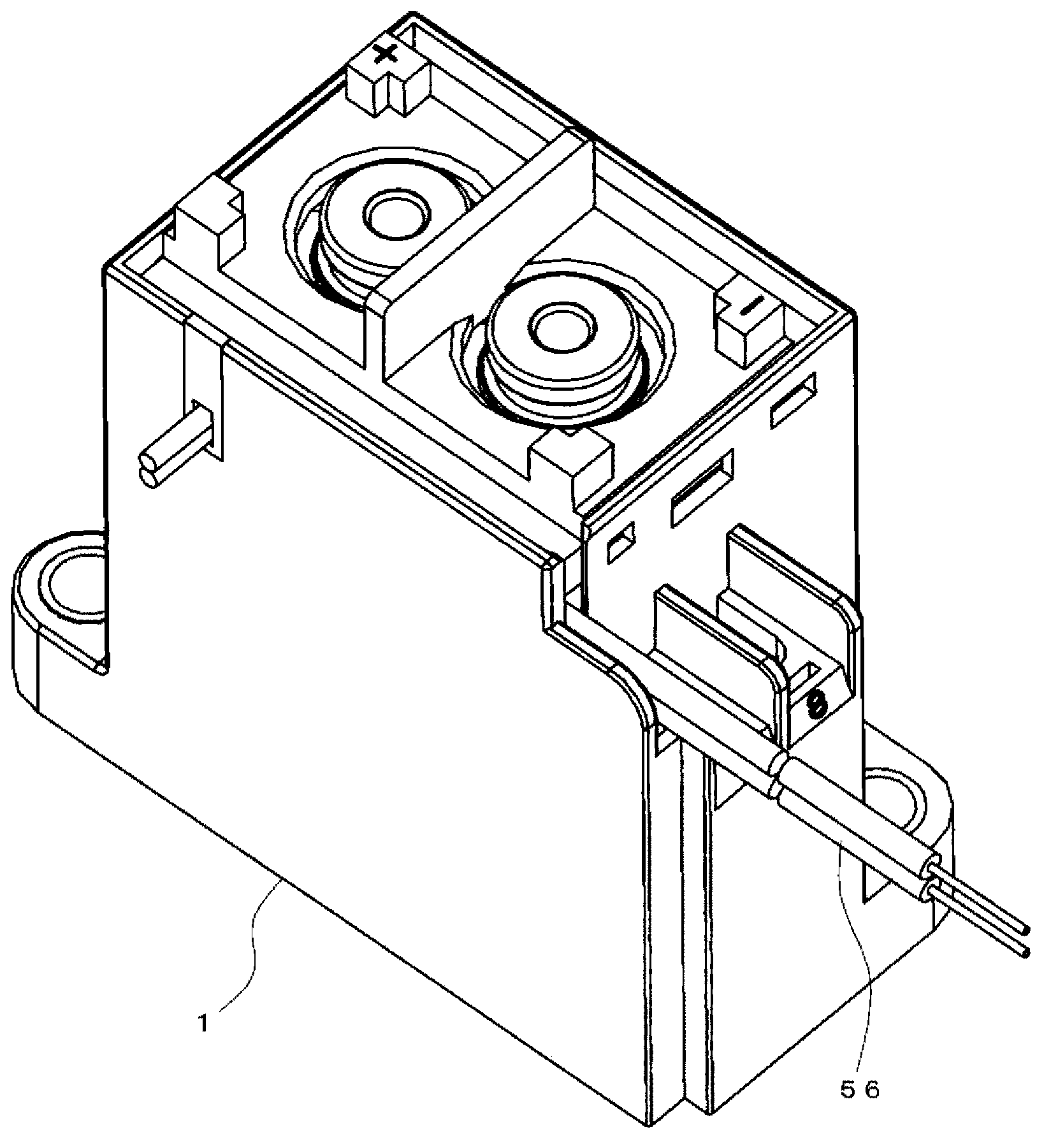
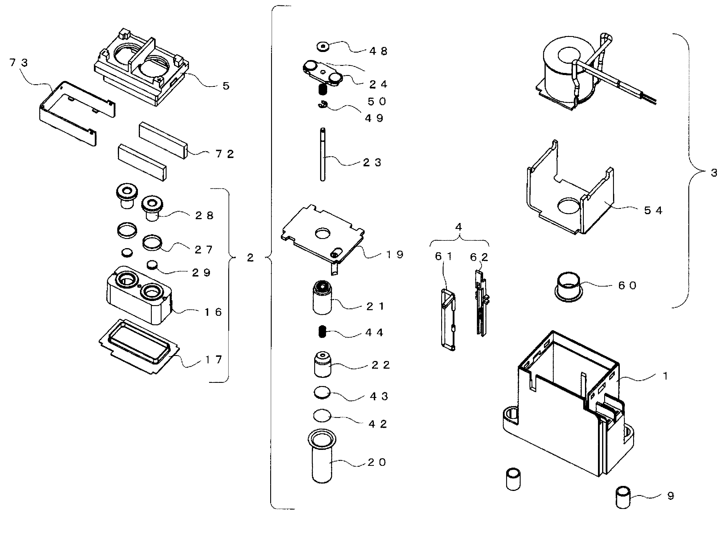
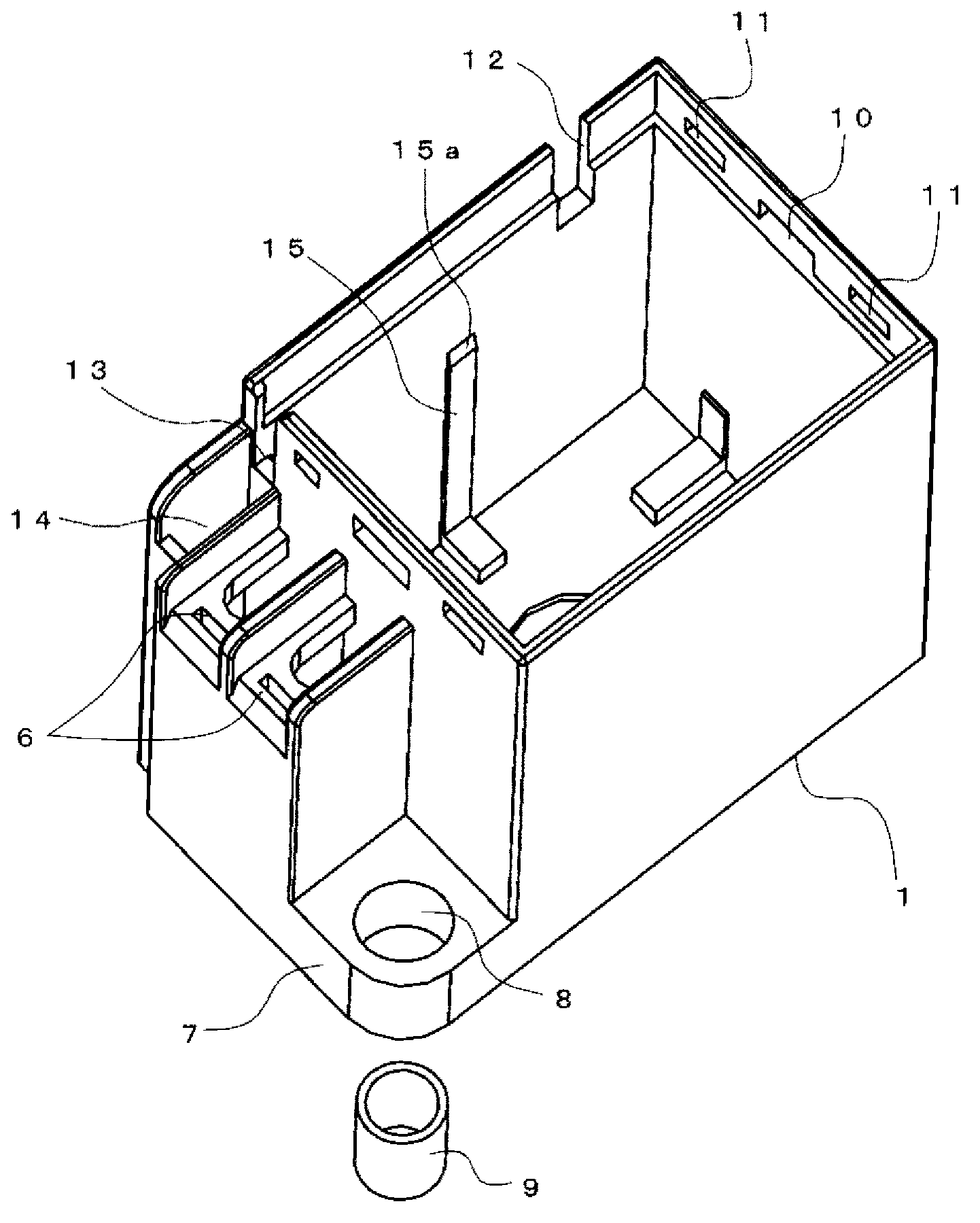
[0040] figure 1 with figure 2 The sealed electromagnetic relay according to this embodiment is shown. The structure of this type of sealed electromagnetic relay is generally such that the contact mechanism part 2 , the electromagnet part 3 and the reed switch part 4 are accommodated in the case 1 and covered with ...


PUM


Abstract

In a box shaped case (1) having an opening part on one surface is housed an electromagnet unit (3) wherein a coil (53) is wound on the outer periphery of a spool (52) having a cylindrical shaped body section (52c) and a yoke is connected to one end part of a stationary iron core (21) disposed on the inner periphery thereof. Part of a magnetic circuit is formed by the stationary iron core (21) and the yoke by applying voltage to the coil (53). A reed switch (61) is disposed along the winding part of the coil (53) parallel to the axial direction of the electromagnet unit (3).

Description

technical field [0001] The invention relates to an electromagnetic relay and a magnetic reed switch installation structure. Background technique [0002] Conventionally, as an electromagnetic relay, there is known an electromagnetic relay having a reed switch for detecting a change in a position where leakage flux flows through a permanent magnet (for example, refer to Patent Document 1). [0003] However, in the above-mentioned prior art electromagnetic relay, the problem of how to configure the reed switch has not been considered. Furthermore, when installing a reed switch in an electromagnetic relay, care must be taken not to cause a large design change or increase in size. [0004] prior art literature [0005] patent documents [0006] Patent Document 1: JP-A-2005-166435 Contents of the invention [0007] The problem to be solved by the invention [0008] An object of the present invention is to provide an electromagnetic relay capable of employing a reed switch ...

Claims


Application Information

Patent Timeline
Patent Type & Authority Applications(China)
IPC IPC(8): H01H50/04H01H50/16H01H50/36
CPCH01H50/16H01H36/0006
Inventor 吉原育广广木和亲川口健介矢野启介
Owner ORMON CORP
Why Eureka
Try Eureka