
Surgical reduction table

A surgical reset and platform technology, applied in surgery, medical science, etc., can solve the problems of manpower consumption, inconvenient operation, complicated operation, etc., and achieve the effect of improving work efficiency, shortening operation time, and reducing trauma area

Inactive Publication Date: 2015-01-14
SUZHOU & SCI & TECH DEV
View PDF6 Cites 0 Cited by
  • Summary
  • Abstract
  • Description
  • Claims
  • Application Information

AI Technical Summary

Problems solved by technology

[0005] The surgical reduction platform with the above structure requires people to pull the bones for radial movement during the operation, and needs to maintain the pulled position until the end of the operation, which not only consumes manpower, but also has instability due to manual operation. , which brings inconvenience and unsafe factors to the doctor's operation. In addition, X-rays need to be used in combination with the observation of the pulled bones during the operation, and the operator will be affected by certain radiation; when the external fixation bracket is used to fix the broken bone When using a pressurizer, only the bone is radially reset. When the bone is seriously dislocated laterally, only the external fixation bracket is used to forcibly align and fix the bone. Sometimes the expected effect cannot be achieved; , when the bone is fixed with an external fixator, due to the large incision on the body surface, the bone at the fracture often has grown and healed, while the surgical incision is still growing and healing; when the bone at the fracture is fixed with an internal fixation plate, it is necessary A variety of auxiliary tools can be used to align the bones at the fracture, which brings a lot of inconvenience to the doctor and complicated operations

Method used


Image

  • Surgical reduction table
  • Surgical reduction table
  • Surgical reduction table

Examples


Embodiment Construction

[0028] The technical solutions of the present invention will be further described in detail below in conjunction with the accompanying drawings and preferred embodiments.

[0029] Such as Figure 4 , Figure 5 , Figure 6 , Figure 7 , Figure 8 , Figure 9As shown, the surgical reduction platform of the present invention includes a storage platform 5 and a base 7, the storage platform 5 is connected above the base 7 by four first support rods 6, and the four first support rods 6 are connected to the storage platform 5, Between the base 7, the connection form of the toothed surface screw pair is adopted, which is convenient for adjusting and locking the position of the storage platform 5. A second support rod 8 is respectively installed on both sides of the front end of the base 7 away from the storage platform 5, and two second support rods 8 are installed. The support rods 8 are respectively connected with the support rods 9 with holes, the pull rods 10 are connected wi...


PUM


Abstract

The invention discloses a surgical reduction table for transverse and radial reduction retraction of fractured bones. The surgical reduction table comprises a holding table and a base. The holding table is connected above the base through four first support rods. The first support rods are connected with the holding table and the base through meshing-surface screw pairs. Two second support rods are mounted on two sides of the front end of the base respectively. Each second support rod is connected with a porous support rod. A pull rod is connected with the upper ends of the porous support rods. A retraction mechanism is mounted between the porous support rods. A lifting reduction mechanism is mounted on the base below the holding table. The surgical reduction table with the structure has the advantages that the surgical reduction table is available for transverse and radial retraction reduction of fractured bones, convenient to operate and high in work efficiency; when an external fixator is used, wound area is greatly reduced for patients; during use of X-ray with the table, the radiation of X-ray upon operators is reduced greatly.

Description

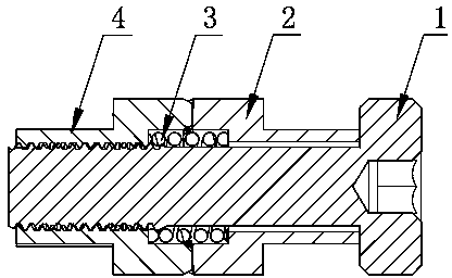
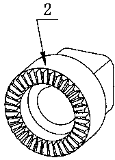
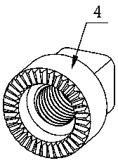
technical field [0001] The invention relates to the field of orthopedic medical devices, in particular to a surgical reduction platform for performing lateral and radial reduction and traction on fractured bones of extremities. Background technique [0002] In orthopedic surgery, when performing surgical treatment on the patient's fractured bone, it is necessary to perform lateral and radial reduction and traction on the fractured bone. The current surgical reduction platform includes a storage platform and a base, and the storage platform is connected by four support rods. On the base, the four support rods, the storage platform, and the base are often connected by a screw pair on the tooth surface. The structure of the screw pair connection on the tooth surface is as follows: figure 1 , figure 2 , image 3 As shown, including bolt 1, there are unthreaded lock tooth block 2 and spring 3 on the bolt 1 in sequence, the threaded lock tooth block 4 is screwed on the outer en...

Claims


Application Information

Patent Timeline
Patent Type & Authority Patents(China)
IPC IPC(8): A61B17/56
Inventor 严飞
Owner SUZHOU & SCI & TECH DEV
Learn More