Grinding fluid distribution arm

A technology of grinding fluid and distributing arm, applied in grinding/polishing equipment, metal processing equipment, manufacturing tools, etc., can solve the problems of difficult to achieve flatness, not distributed, etc.

Inactive Publication Date: 2013-09-11
SHANGHAI INTEGRATED CIRCUIT RES & DEV CENT
View PDF10 Cites 3 Cited by
  • Summary
  • Abstract
  • Description
  • Claims
  • Application Information

AI Technical Summary

Problems solved by technology

[0008] However, in the prior art, the control of the profile and non-uniformity of the wafer is nonlinear through the head and platen speed adjustment, and it is difficult to achieve the required flatness only by the speed adjustment.
Also, adjustments related to slurry are limited to traffic, not distributed

Method used


Image

  • Grinding fluid distribution arm
  • Grinding fluid distribution arm
  • Grinding fluid distribution arm

Examples


Embodiment Construction

[0022] The implementation of the present invention will be described in detail below in conjunction with the drawings and examples, so that the realization process of how to use technical means to solve technical problems and achieve technical effects in the present invention can be fully understood and implemented accordingly.

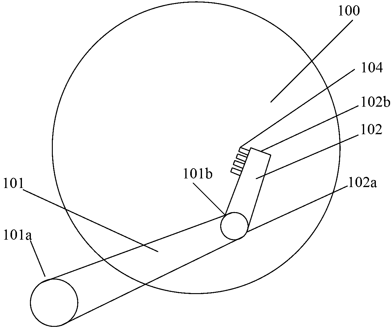
[0023] In the following embodiments of the present invention, by controlling the swing of the first mechanical arm and the swing of the second mechanical arm through the control module, not only the flow control can be realized, but also the relative position between the output port of the grinding liquid and the grinding table can be adjusted, Therefore, the control of the spraying direction of the grinding liquid at the output port of the grinding liquid is realized, and the linear and distributed control are finally realized.

[0024] Such as figure 1 As shown, it is a schematic plan view of the structure of the grinding liquid distribution arm acc...


PUM


Abstract

The invention discloses a grinding fluid distribution arm and belongs to the technical field of semiconductors. The grinding fluid distribution arm is positioned right above a grinding platen and can comprise a first mechanical arm, a second mechanical arm and a control module, the first mechanical arm is connected with one end of the second mechanical arm, a grinding fluid output port is formed at the other end of the second mechanical arm, and the control module controls swing of the first mechanical arm and the second mechanical arm so as to achieve control of grinding fluid spraying directions of the grinding fluid output port. By using the control module for controlling swing of the first mechanical arm and the second mechanical arm, the grinding fluid distribution arm can not only achieve flow control but also adjust opposite positions of the grinding fluid output port and the grinding platen, so that control of the grinding fluid spraying directions of the grinding fluid output port is achieved, and linear and distributive control is achieved finally.

Description

technical field [0001] The invention belongs to the technical field of semiconductors, and in particular relates to a polishing liquid distribution arm. Background technique [0002] With the wide application of 300mm chemical mechanical polishing and the development of 450mm manufacturing process, the application of copper electroless plating (ECP) and copper chemical mechanical polishing (CU-CMP) on the substrate is becoming more and more extensive. However, in terms of throughput, the production of CU-CMP is relatively slow compared with the electroless copper plating (ECP) of the previous station. Therefore, in general, CU-CMP has become a factor that restricts the production capacity of the subsequent copper process. Big bottleneck. [0003] At present, many CMP equipment manufacturers have developed new equipment to improve the throughput of CU-CMP. However, the common solution of these CU-CMP type equipment is to expand the area of ​​the grinding table (platen) and ...

Claims


Application Information

Patent Timeline
Patent Type & Authority Applications(China)
IPC IPC(8): B24B57/02
Inventor 戴文俊
Owner SHANGHAI INTEGRATED CIRCUIT RES & DEV CENT
Why Eureka
Try Eureka