Inner wall clamping device of thin-wall cylindrical micro parts and method

A thin-walled cylinder and clamping device technology, used in microstructure devices, processing microstructure devices, metal processing machinery parts, etc. Effect

Inactive Publication Date: 2013-09-11
INST OF AUTOMATION CHINESE ACAD OF SCI
View PDF7 Cites 1 Cited by
  • Summary
  • Abstract
  • Description
  • Claims
  • Application Information

AI Technical Summary

Problems solved by technology

Since such parts are thin-walled (usually with a wall thickness of 10-200 microns), traditional clamping devices or methods cannot meet the precision assembly requirements in terms of clamping displacement and clamping force control, and the parts are easily damaged during the clamping process. , so there is an urgent need for a device and method for clamping the inner wall of thin-walled cylindrical parts to achieve non-destructive clamping of such parts

Method used


Image

  • Inner wall clamping device of thin-wall cylindrical micro parts and method
  • Inner wall clamping device of thin-wall cylindrical micro parts and method
  • Inner wall clamping device of thin-wall cylindrical micro parts and method

Examples


Embodiment Construction

[0026] In order to make the object, technical solution and advantages of the present invention clearer, the present invention will be described in further detail below in conjunction with specific embodiments and with reference to the accompanying drawings.

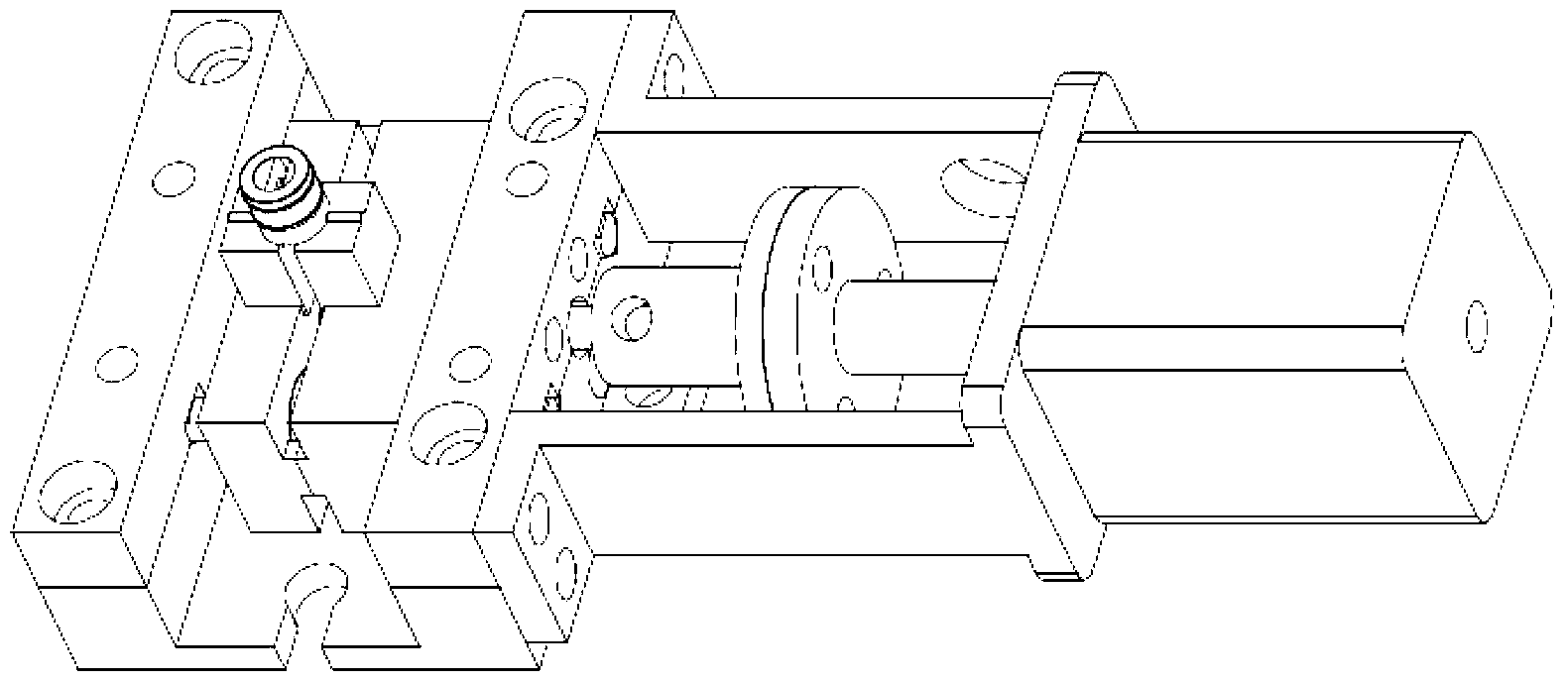
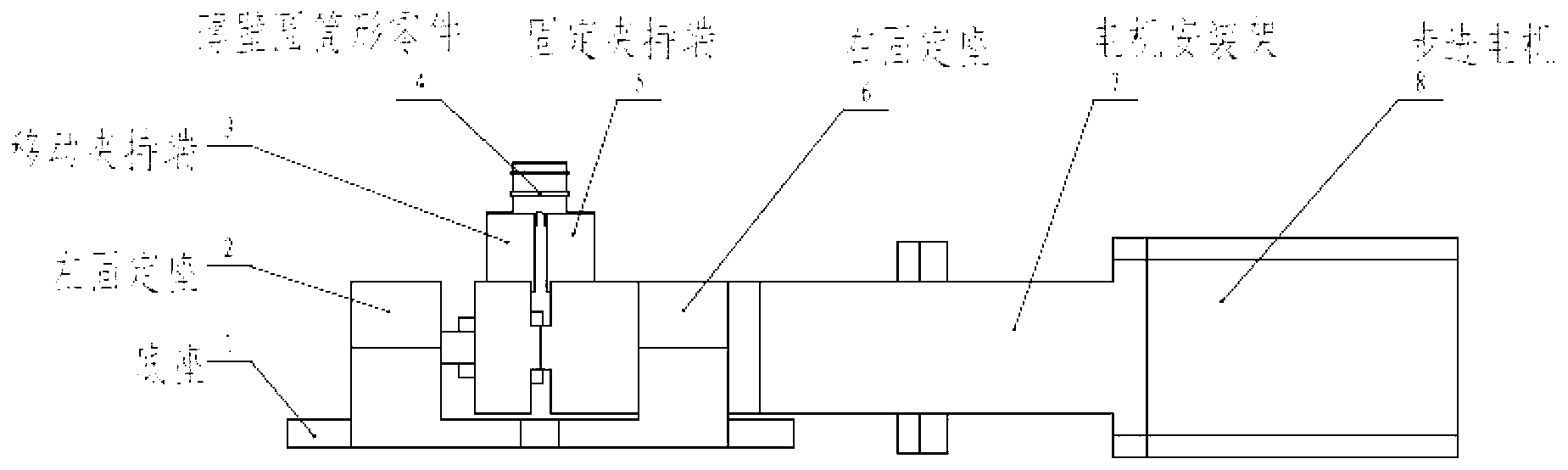
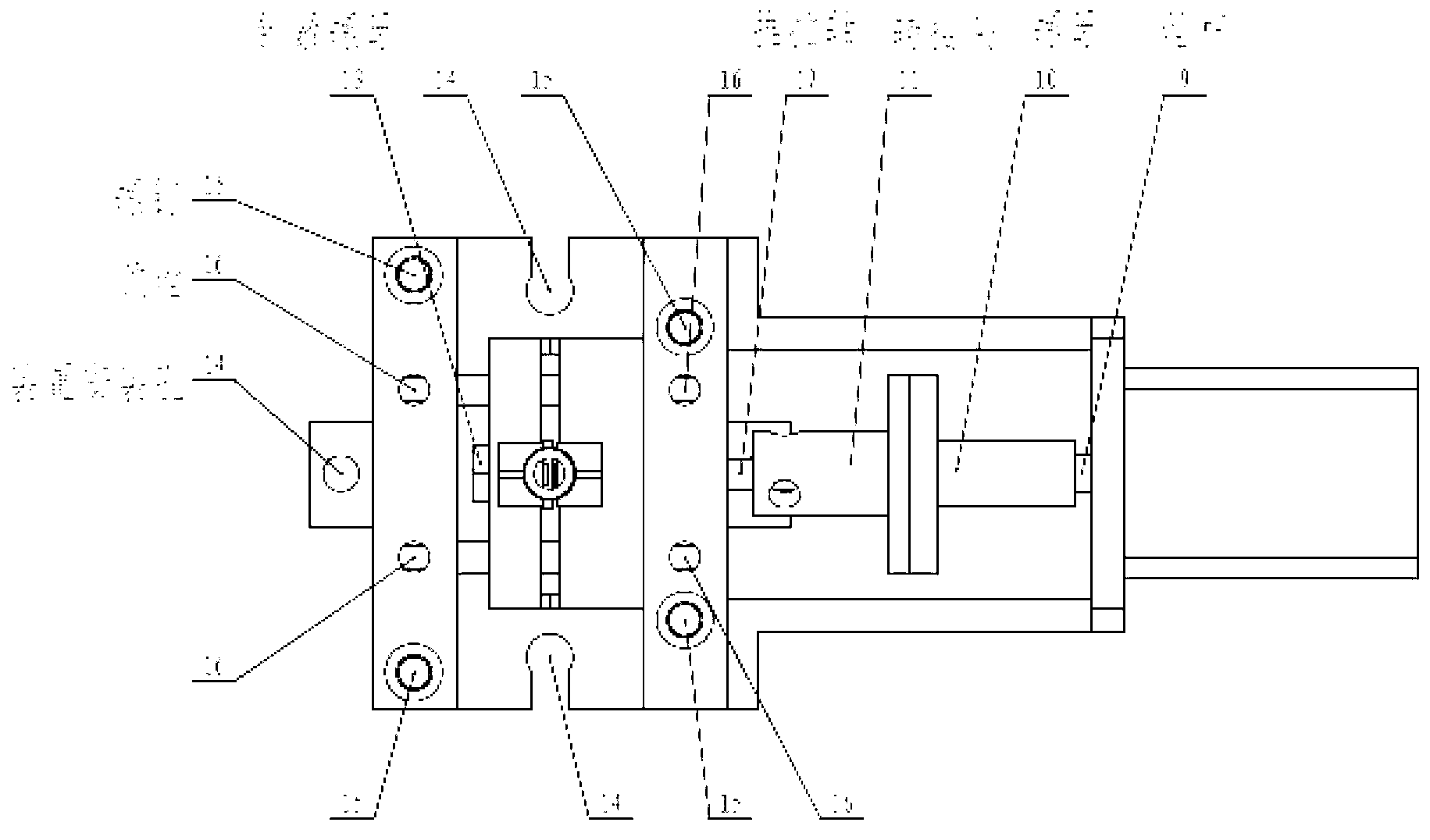
[0027] figure 1 is a three-dimensional view of the clamping device of the present invention, figure 2 It is the front view of the clamping device of the present invention, image 3 It is a top view of the clamping device of the present invention, Figure 4 It is a left view of the clamping device of the present invention, Figure 5 It is a front view of the moving clamping end and the push-pull shaft in the clamping device of the present invention, Image 6 It is the back view of the moving clamping end and the push-pull shaft in the clamping device of the present invention, Figure 7 It is a three-dimensional view of the fixed clamping end in the clamping device of the present invention, such as Figure 1-7 As show...


PUM


Abstract

The invention discloses an inner wall clamping device of thin-wall (10 to 200 micrometers) cylindrical micro parts based on force / position mixed control and a method. The device comprises a base, a left fixing seat, a moving clamping end, a fixed clamping end, a right fixing seat, a motor mounting rack, a stepping motor, a lead screw, a nut, an adapter, a push and pull shaft and two supporting shafts. The device is based on microscopic visual image and clamping applied force information, and drives the moving clamping end through the stepping motor to accomplish the inner wall clamping of parts. A microscopic visual camera is installed above the moving clamping end and the fixed clamping end during a clamping process, the moving clamping end is controlled through the microscopic visual image to get close to a part, after the moving clamping end contacts the inner wall of the clamped part, clamping force applied to the part is detected through a compressive resistance strain gauge, and the feeding of the stepping motor is adjusted according to the applied force, so as to realize the purpose of part lossless clamping.

Description

technical field [0001] The invention relates to the technical field of precision assembly, in particular to a device and method for clamping the inner wall of thin-walled cylindrical micro-parts based on force / position hybrid control. Background technique [0002] There is a type of thin-walled cylindrical parts in the field of precision assembly. During assembly, the outer wall of the part needs to be in contact with other parts, so a clamping device is required to clamp the part from the inner wall. After the part is assembled, the clamping device should be able to be easily removed from the part. Since such parts are thin-walled (usually with a wall thickness of 10-200 microns), traditional clamping devices or methods cannot meet the precision assembly requirements in terms of clamping displacement and clamping force control, and the parts are easily damaged during the clamping process. Therefore, there is an urgent need for a device and method for clamping the inner wal...

Claims


Application Information

Patent Timeline
Patent Type & Authority Applications(China)
IPC IPC(8): B81C3/00
Inventor 张大朋刘松张正涛徐德
Owner INST OF AUTOMATION CHINESE ACAD OF SCI
Why Eureka
Try Eureka