Anaerobic reactor

An anaerobic reactor and coaming technology, which is applied in the field of anaerobic reactors and can solve the problem that the hydraulic load cannot be greatly increased

Active Publication Date: 2013-09-11
OUJI SHANGHAI ENVIRONMENTAL PROTECTION TECH +2
View PDF5 Cites 1 Cited by
  • Summary
  • Abstract
  • Description
  • Claims
  • Application Information

AI Technical Summary

Problems solved by technology

[0005] In view of this, the present invention provides an anaerobic reactor, which is used to solve the problem that the hydraulic load of the existing anaerobic reactor cannot be greatly improved

Method used


Image

  • Anaerobic reactor
  • Anaerobic reactor
  • Anaerobic reactor

Examples


Embodiment Construction

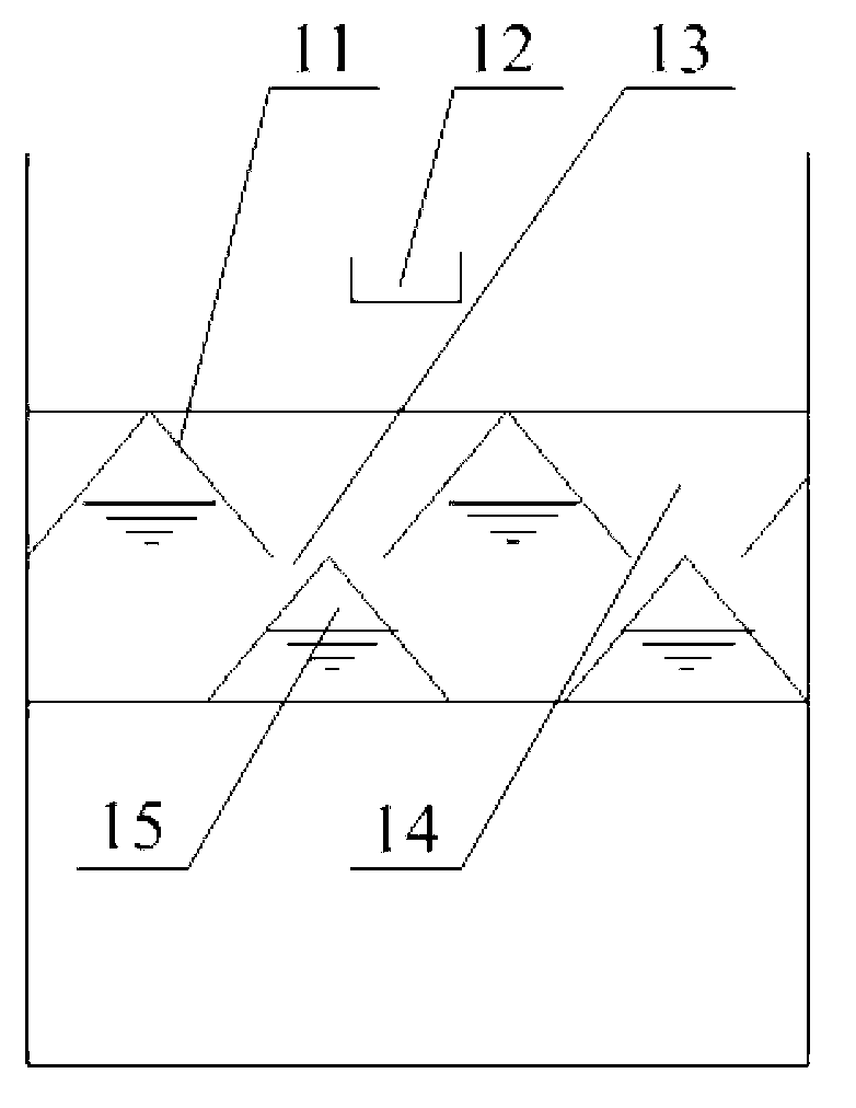
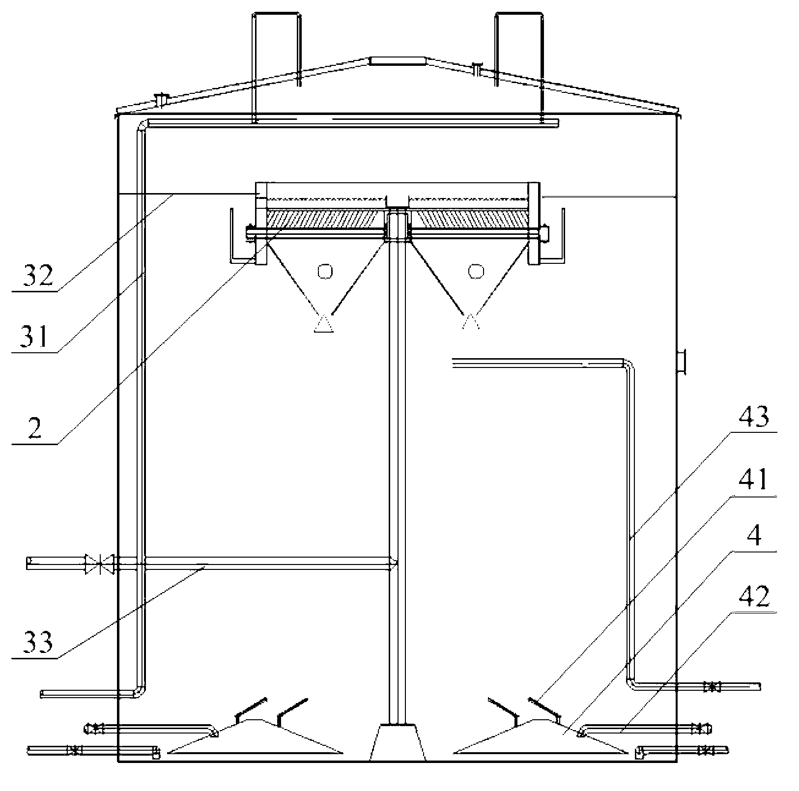
[0031] The core of the present invention is to provide an anaerobic reactor, replace the original three-phase separator with a three-phase separation device, realize the three-phase separation of mud, water and gas, and greatly improve the mud-water separation effect of the reactor, thereby realizing Large increase in hydraulic loading.

[0032] The following will clearly and completely describe the technical solutions in the embodiments of the present invention with reference to the accompanying drawings in the embodiments of the present invention. Obviously, the described embodiments are only some, not all, embodiments of the present invention. Based on the embodiments of the present invention, all other embodiments obtained by persons of ordinary skill in the art without making creative efforts belong to the protection scope of the present invention.

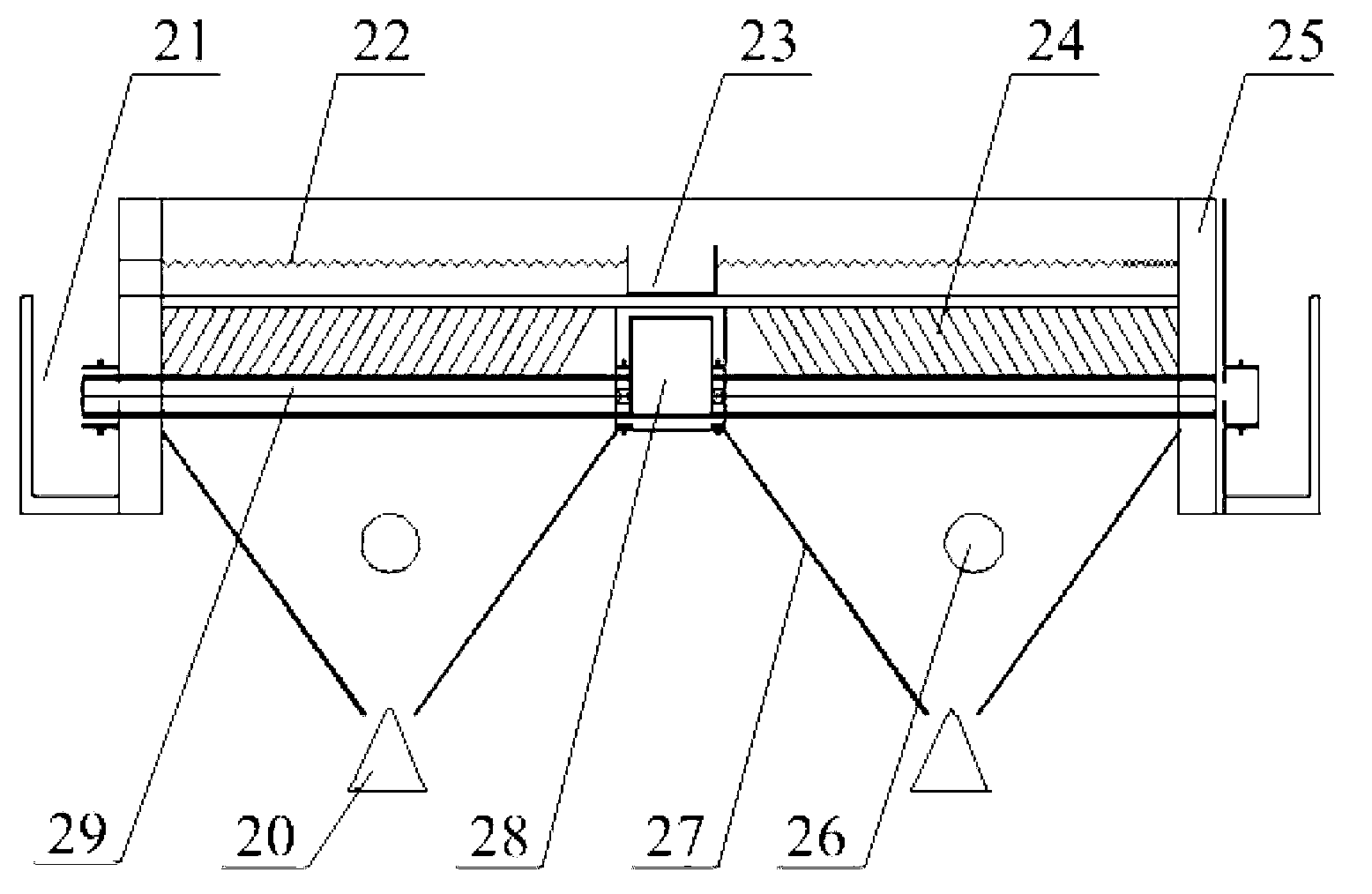
[0033] Please refer to Figure 2 to Figure 4 , figure 2 It is a schematic structural diagram of a three-phase separation...


PUM

PropertyMeasurementUnit
angleaaaaaaaaaa

Abstract

The invention discloses an anaerobic reactor comprising a three-phase separating device, wherein the three-phase separating device comprises a gas releasing device arranged at the outer side of a coaming, and a precipitating device and a water distributing device, which are arranged at the inner side of the coaming, the precipitating device comprises a water channel composed of a plurality of thin plates or pipelines forming included angles with the vertical direction, a water outlet groove is communicated above the precipitating device, a mud bucket is arranged below the precipitating device, the precipitating device and the mud bucket form a hollow cavity, a mud outlet is arranged at the bottom part of the precipitating device, one end of the water distributing device is communicated with the gas releasing device, the other end of the water distributing device is communicated with a water distributing tank at the inner side of the coaming, and a plurality of holes communicated with the hollow cavity are formed in the water distributing tank. Since the water channel composed of the plurality of thin plates or pipelines forming included angles with the vertical direction, muddy water can pass through areas except the plate thicknesses of the thin plates or the wall thicknesses of the pipelines, so that compared with gaps between gas collection covers, the area of the separated sludge flowing back to the reaction region is greatly increased, which improves the muddy water separation effect so as to greatly improve the hydraulic load.

Description

technical field [0001] The invention relates to the technical field of sewage treatment, in particular to an anaerobic reactor. Background technique [0002] Up-flow Anaerobic Sludge Bed / Blanket (UASB for short) reactor is a kind of sewage treatment reactor, also called up-flow anaerobic sludge bed reactor. The UASB reactor consists of three parts: a sludge reaction zone, a sludge-water-gas three-phase separator (including a sedimentation zone) and an air chamber. Anaerobic expanded granular sludge bed (Expanded Granular Sludge Bed, referred to as EGSB) reactor is also a sewage treatment reactor, its structure is similar to UASB reactor, can be divided into water distribution system, reaction zone, three-phase Separation zone and drainage system. Both are anaerobic reactors, and both use a three-phase separator to separate the three-phase separation of the mud-water-gas mixture. [0003] Such as figure 1 as shown, figure 1 It is a structural schematic diagram of a three...

Claims


Application Information

Patent Timeline
Patent Type & Authority Applications(China)
IPC IPC(8): C02F3/28
CPCY02E50/30
Inventor 张广学潘海燕
Owner OUJI SHANGHAI ENVIRONMENTAL PROTECTION TECH
Why Eureka
Try Eureka