An isolated small blade for axial flow compressor rotor expansion stability

An axial-flow compressor and rotor blade technology, which is applied to the components of pumping devices for elastic fluids, mechanical equipment, machines/engines, etc. The effect of improving the flow margin

Active Publication Date: 2018-07-31
NORTHWESTERN POLYTECHNICAL UNIV
View PDF4 Cites 0 Cited by
  • Summary
  • Abstract
  • Description
  • Claims
  • Application Information

AI Technical Summary

Problems solved by technology

This active control method to improve corner separation needs to increase the air circuit, controller, actuator and power supply, and also needs external energy, which limits the applicability of the method to a certain extent.

Method used


Image

  • An isolated small blade for axial flow compressor rotor expansion stability
  • An isolated small blade for axial flow compressor rotor expansion stability
  • An isolated small blade for axial flow compressor rotor expansion stability

Examples


Embodiment Construction

[0018] This embodiment is a kind of isolated small vane with expanded and stabilized rotor of an axial flow compressor.

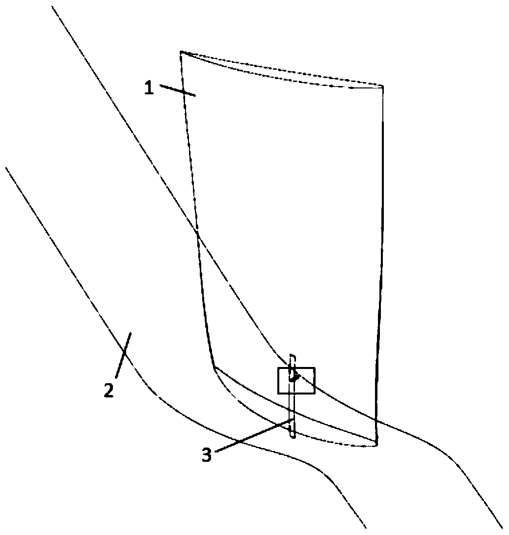
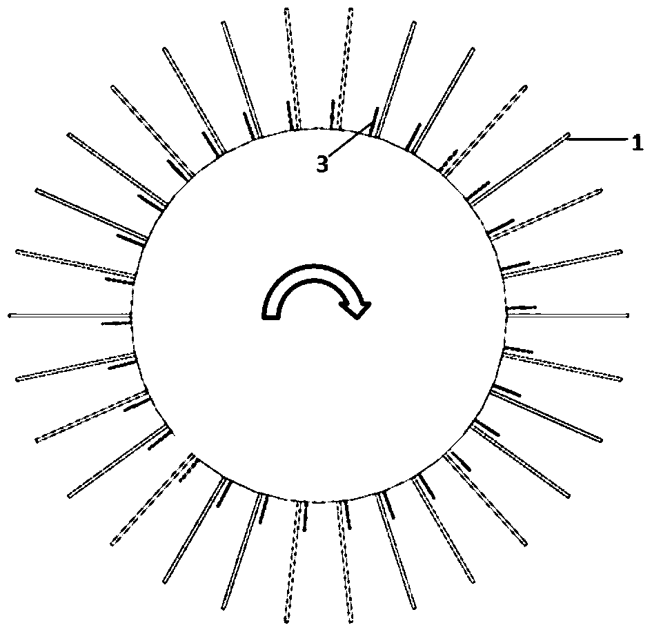
[0019] refer to Figure 1 to Figure 6 In this embodiment, the isolated small blades of the axial flow compressor rotor stabilized are applied to the axial flow compressor rotor. The radius of the compressor rotor casing is 0.149 meters, the radius of the hub is 0.091 meters, and the number of rotor blades is 30. figure 1 As shown in , the lower part is the compressor inlet, and the upper part is the compressor outlet; image 3 Arrows shown in indicate the direction of rotation of the compressor.

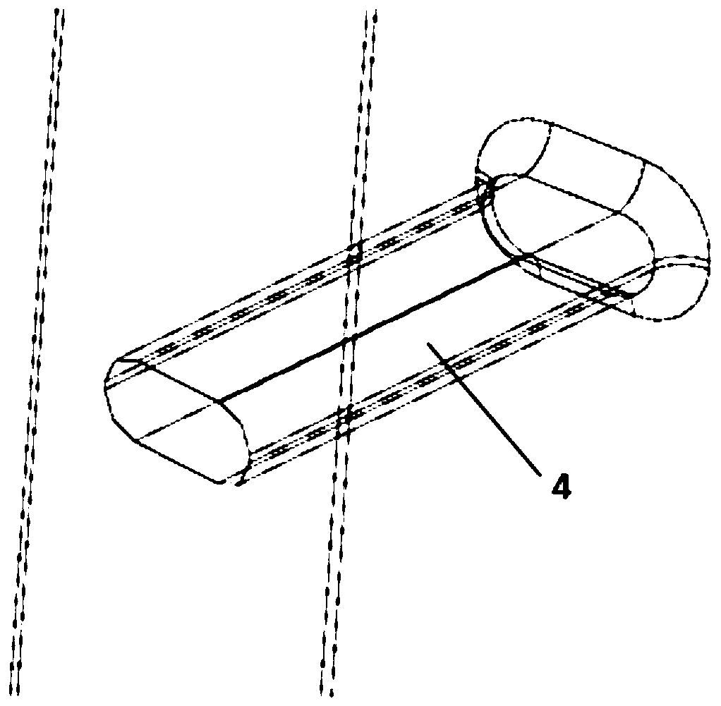
[0020] In this embodiment, isolated small blades 3 are arranged on the compressor rotor blade hub 2, and the blade roots of the isolated small blades 3 are connected to the rotor blade hub 2, and the blade profile installation angle at the blade root is 56°. The axial position of the cascade at the top of the isolated small blade 3 is the same as the axial posit...


PUM


Abstract

The invention discloses a small separation blade for stability enhancement of a rotor of an axial flow compressor. The small separation blade comprises rotor blades, a rotor blade hub, small separation blade bodies and a fixing device; each small separation blade body is installed between every two rotor blades in a rotor blade grating channel, and flow control of the small separation blade bodies over fluid in rotor channels is carried out; the axial positions of the small separation blade bodies are located at the axial chord length positions of rotor blade roots at the 20% positions of the front edges of the rotor blade channels, the circumferential positions are located at the circumferential chord length positions of the rotor blade roots at the 4.6% positions of suction force faces of the rotor blades, and the small separation blade roots are connected with the rotor blade hub; the blade tops of the small separation blade bodies are connected with the suction force faces of the rotor blades through connecting pieces so that the small separation blade bodies can be fixed; and a complex inducing vortex structure generated after air flow flows through the small separation blade bodies will disturb flowing laminar sub-layers of interface layers of the suction force face of a main blade, and strengthening of tubulence energy enables flowing of laminar flow of a boundary layer to be changed into turbulent flow in advance, so that separation of the boundary layer of the laminar flow is restrained or delayed, and the steady operation margin of a compressor is improved.

Description

technical field [0001] The invention relates to the field of flow control of turbomachinery, in particular to an isolated small vane for expanding and stabilizing the rotor of an axial flow compressor. Background technique [0002] In the compressor, due to the effect of the flow reverse pressure gradient, flow separation widely exists on the blade suction surface, and with the decrease of the compressor flow rate, the flow separation becomes more and more serious, and to a certain extent, the separated fluid clogs The passage of the compressor makes the compressor enter an unstable working state, which seriously affects the performance of the compressor. Therefore, it is necessary to conduct research on flow control technology to control the flow separation of the compressor and improve its stability margin. Flow control technology uses the interaction between fluids to control the flow state by changing the local flow. It can effectively suppress flow separation and expa...

Claims


Application Information

Patent Timeline
Patent Type & Authority Patents(China)
IPC IPC(8): F04D29/38
CPCF04D29/384
Inventor 吴艳辉刘军张皓光安光耀陈智洋
Owner NORTHWESTERN POLYTECHNICAL UNIV
Why Eureka
Try Eureka