Axial-flow compressor rotor with flow-guiding small blades

An axial flow compressor and small vane technology, which is applied to the components of the pumping device for elastic fluids, mechanical equipment, machines/engines, etc. Convenience and the effect of improving the flow margin

Inactive Publication Date: 2016-09-07
NORTHWESTERN POLYTECHNICAL UNIV
View PDF7 Cites 2 Cited by
  • Summary
  • Abstract
  • Description
  • Claims
  • Application Information

AI Technical Summary

Problems solved by technology

In the literature, blade tip air injection technology is used to improve the performance of the compressor rotor. Although the stable operating range of the compressor rotor is significantly improved, the air jet transposition requires an external air source and a series of control components. The implementation process is complicated and the practicality is low.

Method used


Image

  • Axial-flow compressor rotor with flow-guiding small blades
  • Axial-flow compressor rotor with flow-guiding small blades
  • Axial-flow compressor rotor with flow-guiding small blades

Examples


Embodiment Construction

[0013] The technical solutions of the present invention will be further described below in conjunction with specific implementation examples.

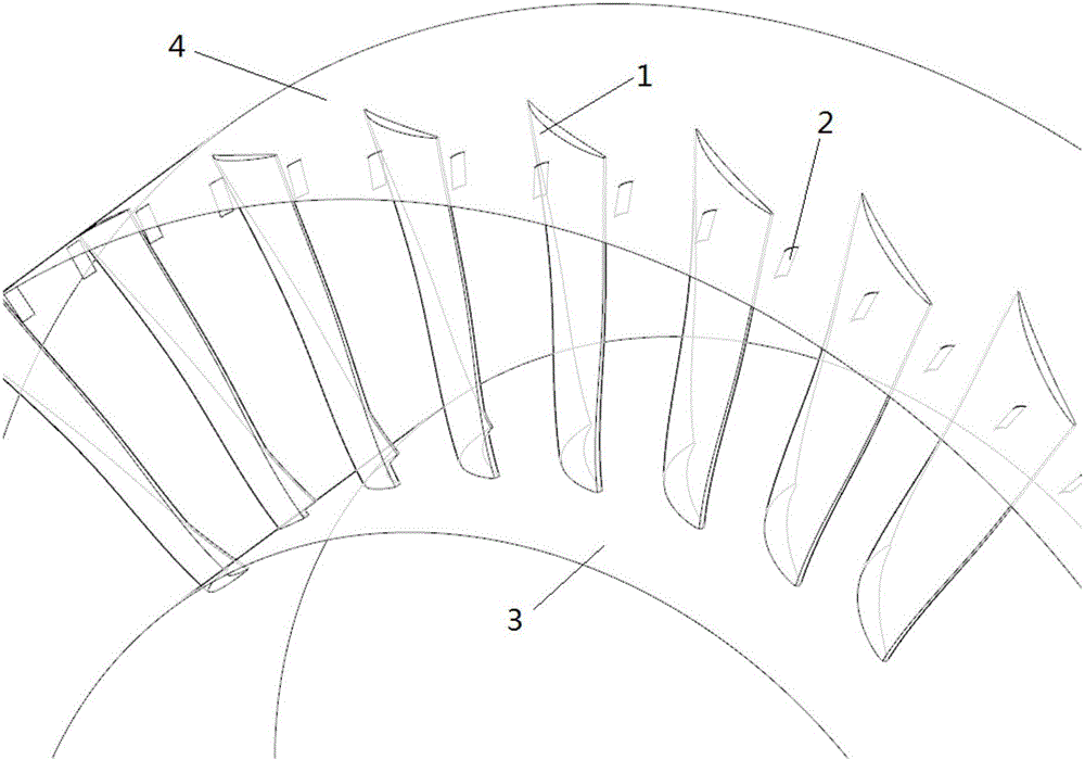
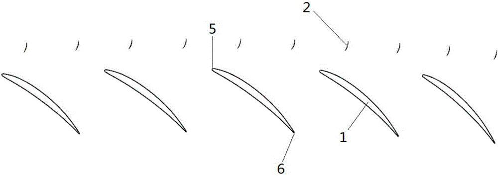
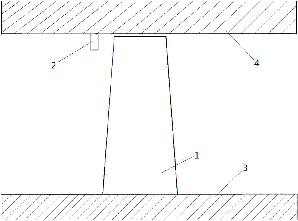
[0014] 1. See Figure 1-Figure 3 , an axial flow compressor rotor with guide vanes, including axial compressor rotor blades, axial compressor hub, casing and guide vanes, which is characterized in that the guide vanes are installed on the rotor blades On the casing upstream of the top channel, the chord length of the small blade is 1-2 orders of magnitude lower than that of the rotor blade, that is to say, the chord length is 1%-20% of the rotor blade, and the height is 5%-15% of the rotor blade height. Evenly distributed on the casing in the circumferential direction, the number is 1-2 times the number of rotor blades, and the axial position is located at 10%-30% of the blade tip chord length upstream of the blade tip passage. The small blade root is welded on the casing.

[0015] The small blades are straight blades with a pair of ...


PUM


Abstract

The invention provides an axial-flow compressor rotor with flow-guiding small blades. The axial-flow compressor rotor comprises rotor blades, a casing and a hub, wherein the flow-guiding small blades, bi-arc straight blades, are further mounted on the casing, and the blade roots of the flow-guiding small blades are connected with the upstream part of the casing and circumferentially and uniformly distributed on the casing; and the axial positions of the flow-guiding small blades are located at the blade tip chord length, 10-30% of the upstream parts, of the blade tips of the rotor blades, and the bending directions of the flow-guiding small blades are in the rotational directions of the rotor blades (1). According to the axial-flow compressor rotor, the attack angles and the diffusion factors of channel air flow in the blade tip areas are reduced, the load of the blade tip areas is reduced, and flow channels are prevented from being blocked by leakage flow at the blade tips of the rotor blades. The stable working scope of the compressor rotor is expanded, and the flow allowance of a compressor is improved. Compared with the blade tip jet technology, the technology adopted by the invention has the advantages that the guide blade processing casing is convenient to mount and simple in structure, external energy supply is not needed, and the industrial manufacturing cost is lowered.

Description

technical field [0001] The invention relates to the field of flow control of impeller machinery, in particular to an axial flow compressor rotor with flow guide vanes. Background technique [0002] For modern aero-engines, it is usually required that its fans and inlet-stage compressors can work stably under various complex flow fields. However, when the compressor inlet flow decreases, the interface between the clearance leakage flow and the main flow of the compressor rotor moves upstream of the rotor channel. When the inlet flow rate is further reduced, the gap leakage flow flows out of the rotor channel in reverse, forming a blockage area at the tip of the blade, causing the compressor to enter an unstable working condition such as rotating stall and surge, and the performance of the compressor deteriorates sharply, seriously affecting the normal operation of the engine . In order to improve the stable working range of the compressor rotor, the document "Compressor Sta...

Claims


Application Information

Patent Timeline
Patent Type & Authority Applications(China)
IPC IPC(8): F04D29/32F04D29/54
CPCF04D29/321F04D29/324F04D29/541
Inventor 刘军吴艳辉安光耀陈智洋彭文辉杨玄州
Owner NORTHWESTERN POLYTECHNICAL UNIV
Why Eureka
Try Eureka