Glass substrate cutting system

A glass substrate and cutting system technology, applied in glass cutting devices, glass manufacturing equipment, conveyors, etc., can solve the problems of scrapped finished glass substrates, scratches on cutting surfaces, easy jumping or sliding, etc., to achieve increased contact area, The force is uniform and stable, and the effect of avoiding being scratched

Active Publication Date: 2013-09-11
SHENZHEN CHINA STAR OPTOELECTRONICS TECH CO LTD
View PDF4 Cites 20 Cited by
  • Summary
  • Abstract
  • Description
  • Claims
  • Application Information

AI Technical Summary

Problems solved by technology

The chuck 160 is controlled by a cylinder (not shown in the figure), which makes it difficult to ensure the consistency and stability of the chuck 160
Moreover, the contact area between the chuck 160 and the remaining material part 112b is relatively small by clamping, which further causes uneven force on the remaining material part 112b, so that when the remaining material part 112b is separated from the next finished product part 112a, it is easy to jump or slide , causing scratches on the cut surface of the finished part 112a, and even scrapping the finished glass substrate

Method used


Image

  • Glass substrate cutting system
  • Glass substrate cutting system
  • Glass substrate cutting system

Examples


Embodiment 2

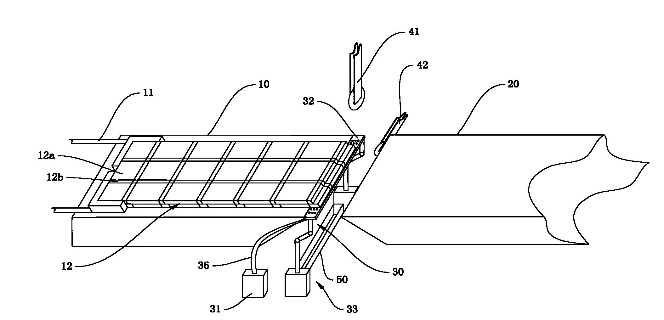
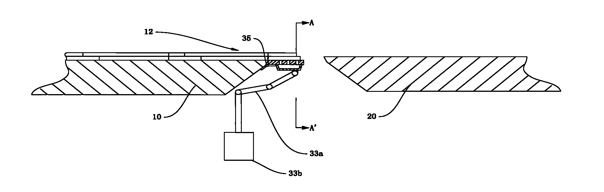
[0043] In this example, if Figure 7 As shown, the suction plate 32 of this unloading device 30 can also not be directly hinged to the front end of the upstream suction table 10, but moves as a whole under the drive of the mechanical arm 33a, so as to complete the separation of the suction residual part 12b from the original glass substrate 12 and unload.

[0044] In addition, a roller 70 is added above the glass substrate 12 , opposite to the lower cutter head 42 , so that the cutting sequence of the upper cutter head 41 and the lower cutter head 42 can be adjusted to meet the needs of glass substrates 12 of different shapes. For example, the CF board of the glass substrate 12 can be cut by using the lower cutter head 42 first. A pair of balancing forces keeps the glass substrate 12 from being damaged. After the cutting of the CF board is completed, the suction plate 32 is raised to be flush with the surface of the upstream suction table 10, and the upper cutter head 41 is ...


PUM


Abstract

The invention provides a glass substrate cutting system. The glass substrate cutting system comprises an upstream suction platform, a movable device, an upper cutter head and a lower cutter head, wherein a downstream suction platform is arranged in front of the upstream suction platform at interval and is used for receiving a finished-product part cut from a glass substrate; the movable device is used for pushing the glass substrate to move from the upstream suction platform to the downstream suction platform; the upper cutter head and the lower cutter head are arranged between the upstream suction platform and the downstream suction platform. The glass substrate cutting system further comprises an unloading device arranged between the upstream suction platform and the downstream suction platform; the unloading device comprises a vacuum pump, a suction plate provided with a through hole, and a displacement component connected with the suction plate, wherein the bottom of the suction plate is connected with an adsorption cavity; the adsorption cavity is respectively communicated with the through hole and the vacuum pump so that a residual material part placed on the surface of the suction plate is adsorbed on the suction plate; and the displacement component is used for driving the suction plate adsorbed with the residual material part to rotate, so as to remove the residual material part. According to the glass substrate cutting system, the scratches of a cutting face of the glass substrate cutting system can be effectively avoided and the quality of a cut finished-product is improved.

Description

technical field [0001] The invention relates to the technical field of liquid crystal panel production, in particular to a glass substrate cutting system for a liquid crystal panel. Background technique [0002] The general structure of the existing glass substrate includes: a TFT substrate and a CF substrate laminated up and down, and liquid crystal molecules poured between the TFT substrate and the CF substrate. The prepared glass substrates are then cut and separated according to the size of different displays. The existing cutting technology is to use an upper cutter head and a lower cutter head to respectively cut the TFT substrate and the CF substrate at the gap between the upstream suction table and the downstream suction table. [0003] Such as figure 1 As shown, the raw material of glass substrate 112 is preset with a cutting line, which is divided into finished product part 112a (larger area) and surplus material part 112b (smaller area). Driven by moving device ...

Claims


Application Information

Patent Timeline
Patent Type & Authority Applications(China)
IPC IPC(8): C03B33/03
CPCC03B33/033B65G2249/04B65G2249/045C03B33/03
Inventor 黄海波
Owner SHENZHEN CHINA STAR OPTOELECTRONICS TECH CO LTD
Why Eureka
Try Eureka