Through tubing perforating bullet case and through tubing perforating bullet

A technology of perforating shells and perforating bullets, applied in the field of perforating bullets, can solve the problems of easy deformation and high processing precision requirements, and achieve the effects of convenient processing, high assembly precision and fast installation

Active Publication Date: 2013-09-11
宁波宇恒能源科技有限公司
View PDF5 Cites 8 Cited by
  • Summary
  • Abstract
  • Description
  • Claims
  • Application Information

AI Technical Summary

Problems solved by technology

However, the perforating bullets assembled from the perforating bullet casings need to be equipped with a perforating gun, and the processing accuracy of t

Method used


Image

  • Through tubing perforating bullet case and through tubing perforating bullet
  • Through tubing perforating bullet case and through tubing perforating bullet
  • Through tubing perforating bullet case and through tubing perforating bullet

Examples


Example Embodiment

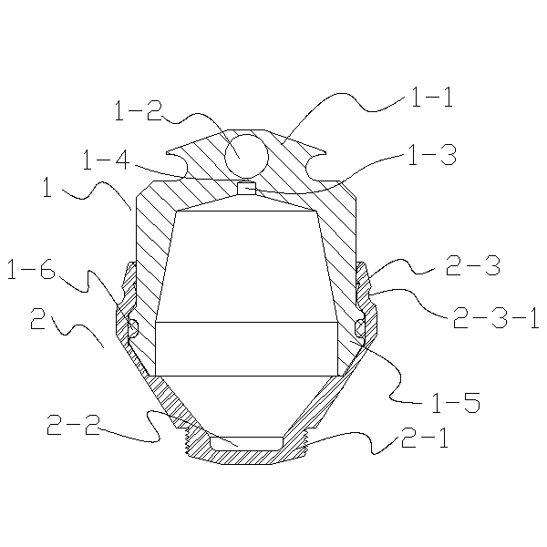
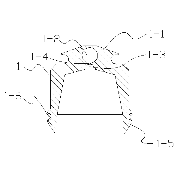
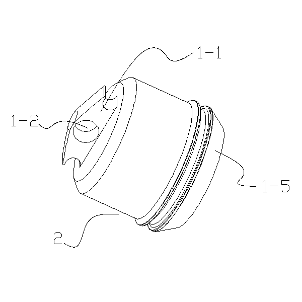
[0024] Embodiment 1: The through-tubing perforating bullet shell of this embodiment is as figure 1 , 2 , 3, 4, and 5, including perforating cartridge case 1 and perforating cartridge cap 2. Perforating cartridge case 1 and perforating cartridge cap 2 are buckled together, and O is installed between perforating cartridge case 1 and perforating cap 2 Type sealing ring 1-6.

[0025] The open end of the perforating bullet cap 2 is provided with a narrowing-shaped bullet shell buckle portion 2-3, and the bullet shell buckle portion 2-3 is pressed with an annular elastic inner concave portion 2-3-1, and an inner concave portion 2-3-1. The outer wall of 1 is concave inward to form a groove, the inner wall of the inner concave portion 2-3-1 is convex inward to form a convex ring, and the outer wall of the open end of the perforating cartridge 1 is provided with a trapezoidal ring-shaped bullet cap buckling portion 1-5 , The cap buckling part 1-5 is made with a slot hole for installing t...

Example Embodiment

[0028] Embodiment 2: The through-tubing perforating bullet shell of this embodiment is as Image 6 As shown, the perforating cartridge case 1 is made of 40CR material. An inner cover 3 is provided on the cavity wall of the inner cavity of the perforating cartridge case 1. The inner cover 3 is made of ZN material, and the inner cover 3 is closely attached to the perforating cartridge case 1. On the cavity wall of the inner cavity, the surface roughness of the joint between the cavity wall of the perforating cartridge case 1 and the outer surface of the inner cover 3 is Ra6.3-12.5. Other technical features are the same as the perforating cartridge case 1 of implementation 1.

[0029] The through-tubing perforating bullet of this embodiment includes a through-tubing perforating bullet shell. The inner cavity of the perforating bullet shell 1 is equipped with a charge cover 5, and the inner cavity wall of the perforating shell 1 and the charge cover 5 are compressed with Dynamite 4....


PUM

PropertyMeasurementUnit
Thicknessaaaaaaaaaa

Abstract

The invention discloses a through tubing perforating bullet case and a through tubing perforating bullet. The through tubing perforating bullet case comprises a perforating bullet case part and a perforating bullet cap which are connected in a buckling manner, wherein the perforating bullet case part comprises a perforating bullet case body with an inner cavity; a raised detonating cord mounting part is arranged on the end face of one end of the perforating bullet case body; a detonating cord hole used for mounting a detonating cord is formed in the side surface of the detonating cord mounting part; a detonating explosive hole is formed in a wall, positioned under the detonating cord hole, of the inner cavity of the perforating bullet case body; the perforating bullet cap comprises a perforating bullet cap body with an inner cavity; a raised external thread part is arranged at one end of the perforating bullet cap body; a jet channel is arranged in the external thread part; one end of the jet channel is closed; and the other end of the jet channel is communicated with the inner cavity of the perforating bullet cap body. The through tubing perforating bullet case and the through tubing perforating bullet are not required to be matched with a perforating gun, and are convenient to process, quick to mount, and higher in assembling precision.

Description

[0001] technical field [0002] The invention relates to the field of perforating bullets, in particular to a casing of a perforating bullet passing through an oil pipe and the perforating bullet. Background technique [0003] The Chinese patent with the application number 200920243436.8 discloses a perforating charge for oil and gas wells with high hole density and deep penetration of the perforator, including a shell and a liner. The perforating end of the shell is composed of a cylindrical section, a small cone section and a large cone section. The diameter of the cylindrical section is 9mm-12mm, the taper of the small cone section is 125°-140°, and the taper of the large cone section is 45°-55°; The body cavity and cylindrical cavity are formed, the taper of the small cone cavity is 90°-110°, the taper of the large cone cavity is 42°-50°, and the diameter of the cylindrical cavity is 46mm-50mm. However, the perforating bullets assembled from the perforating bullet casin...

Claims


Application Information

Patent Timeline
IPC IPC(8): E21B43/119E21B43/116
Inventor 王志潮苏华
Owner 宁波宇恒能源科技有限公司
Why Eureka
Try Eureka