Power supply cooling unit

A cooling device and power supply technology, which is applied in the field of heat exchange, can solve the problems of insufficient cooling, fixed channels, and excess cooling, etc., and achieve the effects of realizing heat exchange, prolonging the flow time, and improving heat exchange efficiency

Inactive Publication Date: 2013-09-11
ZHEJIANG SANHUA AUTOMOTIVE COMPONENTS CO LTD
View PDF9 Cites 8 Cited by
  • Summary
  • Abstract
  • Description
  • Claims
  • Application Information

AI Technical Summary

Problems solved by technology

At this time, due to the immutability of the channel, it is possible that the cooling in the middle is insufficient, while the cooling in other places is excessive.

Method used


Image

  • Power supply cooling unit
  • Power supply cooling unit
  • Power supply cooling unit

Examples


Embodiment Construction

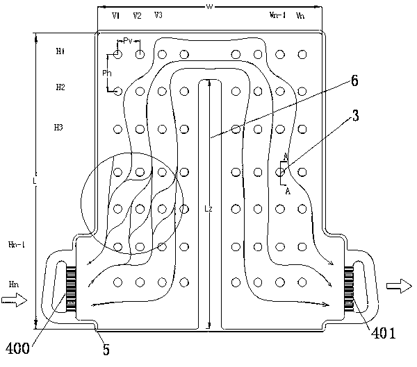
[0031] In the electric vehicle power cooling device of the present invention, by providing a barrier section separating the inlet end and the outlet end of the cooling device, the flow path of the cooling liquid is U-shaped, which maximizes the flow time of the cooling liquid in the cooling device. The present invention also obstructs the flow of the cooling liquid by setting the spoiler pits on the plates, increases the flow resistance of the cooling liquid and further extends the flow path of the cooling liquid, and the cooling liquid is continuously divided and merged during the flow of the cooling liquid, so that the cooling liquid In the flow process, it is fully mixed to maximize the heat exchange between the coolant and the power supply. The present invention is described in detail below in conjunction with the drawings:

[0032] In the present invention, such as figure 1 As shown, the cooling device shown in the figure is roughly rectangular, with the upper and lower side...


PUM


Abstract

The invention relates to a power supply cooling unit which comprises at least two plates (a first plate (1) and a second plate (2)) which are arranged in a laminated mode, wherein the peripheries of the plates are fixedly connected in a hermetic mode; a coolant flow channel is arranged between every two plates; the central heat exchange region of at least one plate in every two adjacent plates is provided with a surface pattern and a barrier section (6); the length of the barrier section (6) is less than that of the plate; after the adjacent plates are fixedly connected in a hermetic mode, the barrier sections (6) of the adjacent plates mutually compact and contact, or the barrier section (6) on one plate and the other plate mutually compact and contact, so that the coolant flow channel is intercepted into a U-shaped route by the barrier section; and the surface pattern sinks to the inside of the coolant flow channel, and is arranged approximately along the U-shaped flow route of the coolant, thereby maximally prolonging the flow time of the coolant in the cooling unit.

Description

Technical field [0001] The invention relates to the field of heat exchange, and more specifically, to a power supply cooling device. Background technique [0002] Electric vehicles are the development direction of new energy vehicles in the future. Electric cars rely on batteries to generate all power sources. However, the battery of an electric vehicle is generating a lot of heat. If the heat is not effectively brought out, the temperature of the battery will become higher and higher. If it exceeds its normal use temperature, it will cause the battery to overheat or even burn out. [0003] Most of the existing battery cooling devices are cooling devices with a channel-type structure, that is, the cooling device includes a number of channels evenly distributed and communicating with the coolant inlet and outlet. In addition, most of the channels of the existing battery cooling devices are U-shaped in order to achieve the largest cooling liquid circulation area in the smallest spa...

Claims


Application Information

Patent Timeline
Patent Type & Authority Applications(China)
IPC IPC(8): H01M10/50B60K11/02
Inventor 不公告发明人
Owner ZHEJIANG SANHUA AUTOMOTIVE COMPONENTS CO LTD
Why Eureka
Try Eureka