Equal-thickness in-plane continuous plate strip bending method

An internal bending, continuous plate technology, applied in metal rolling and other directions, can solve the problems of reduced material properties and low material utilization, and achieve the effects of improving mechanical properties, avoiding forming defects, and simple operation

Active Publication Date: 2013-09-18
NORTHWESTERN POLYTECHNICAL UNIV
View PDF5 Cites 6 Cited by
  • Summary
  • Abstract
  • Description
  • Claims
  • Application Information

AI Technical Summary

Problems solved by technology

[0006] In order to overcome the defects of the existing technology in the prior art, such as the defects of forming rings with equal thickness in-plane bending, the low utili...

Method used


Image

  • Equal-thickness in-plane continuous plate strip bending method
  • Equal-thickness in-plane continuous plate strip bending method
  • Equal-thickness in-plane continuous plate strip bending method

Examples


Embodiment 1

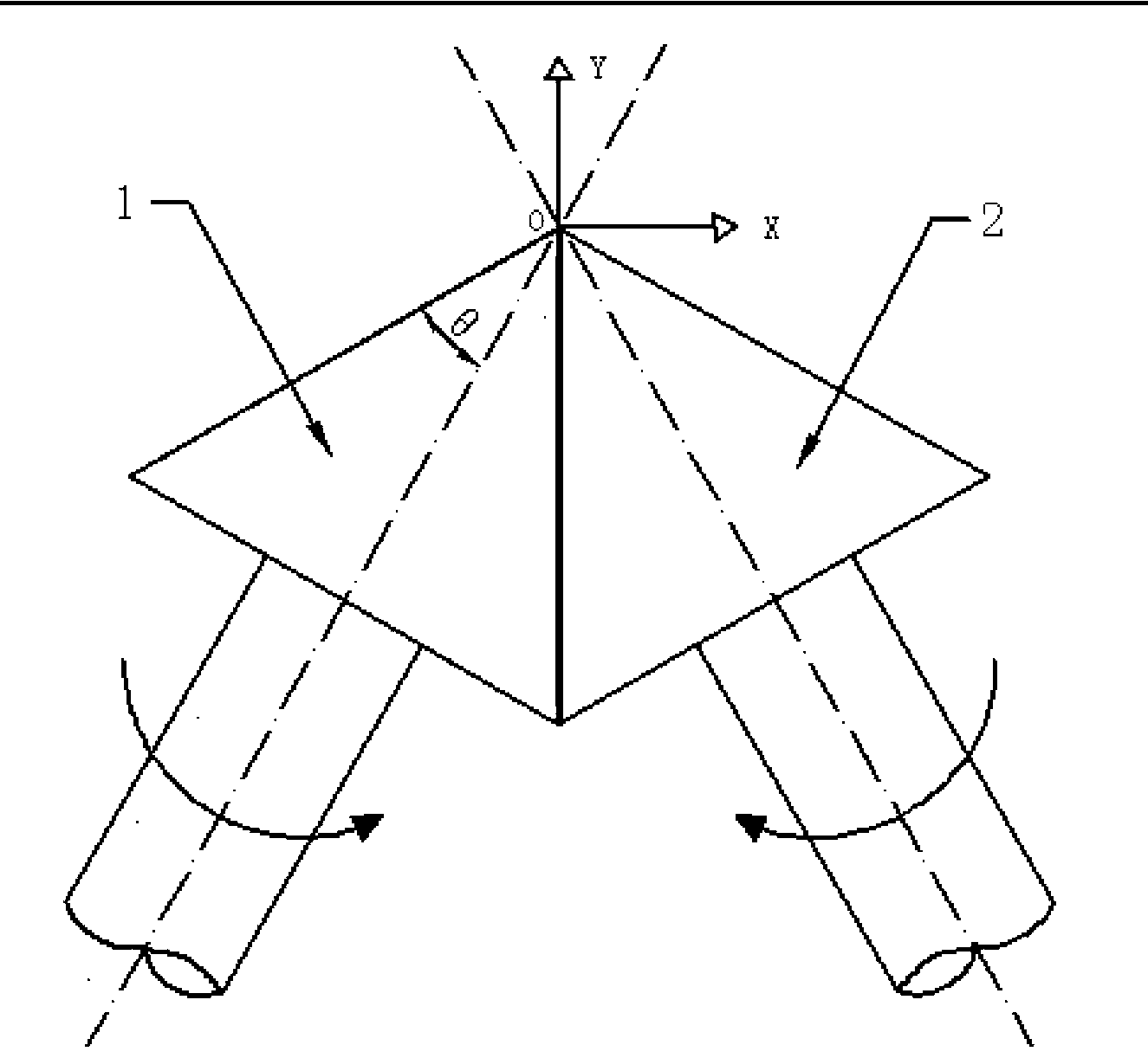
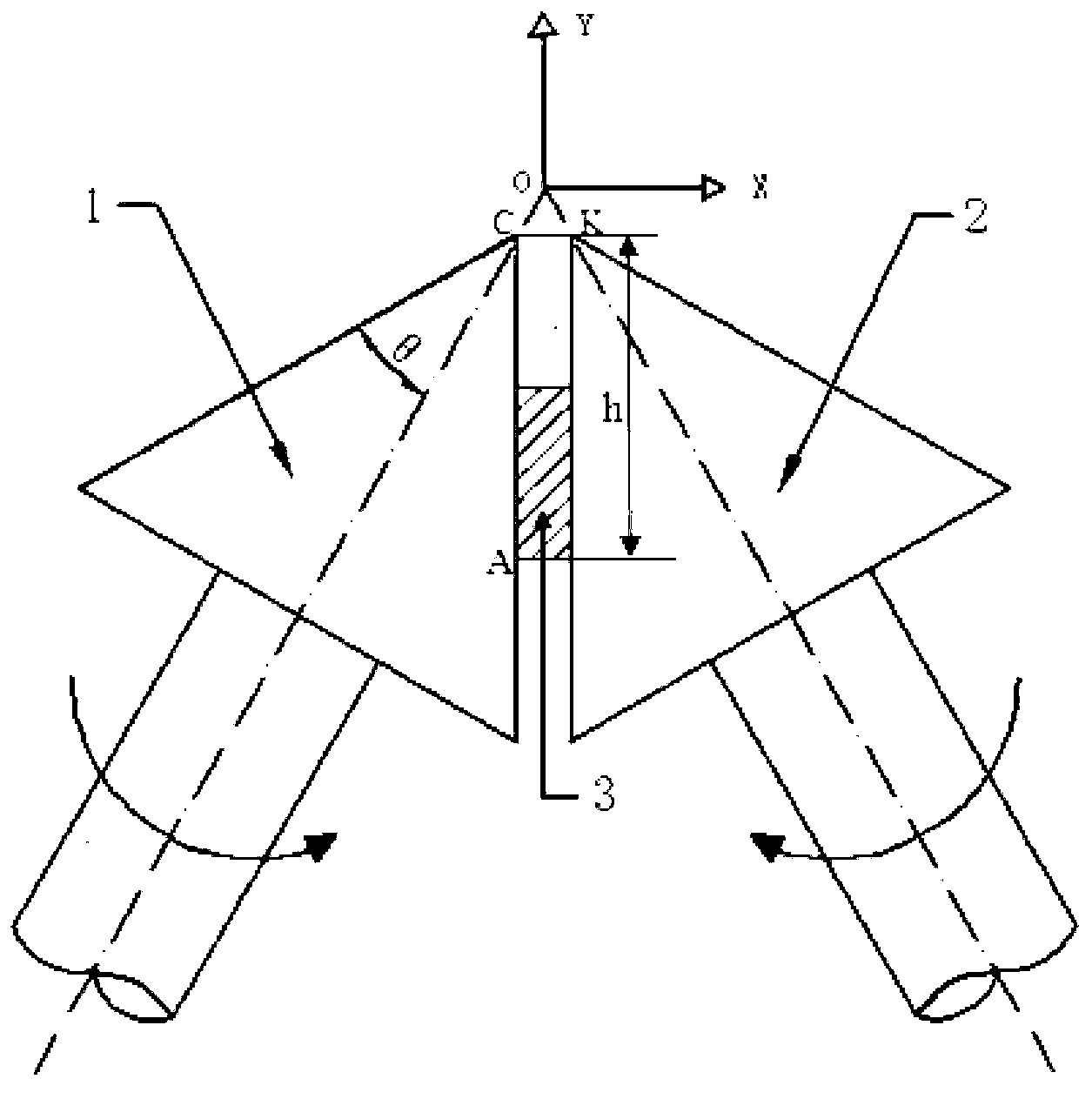
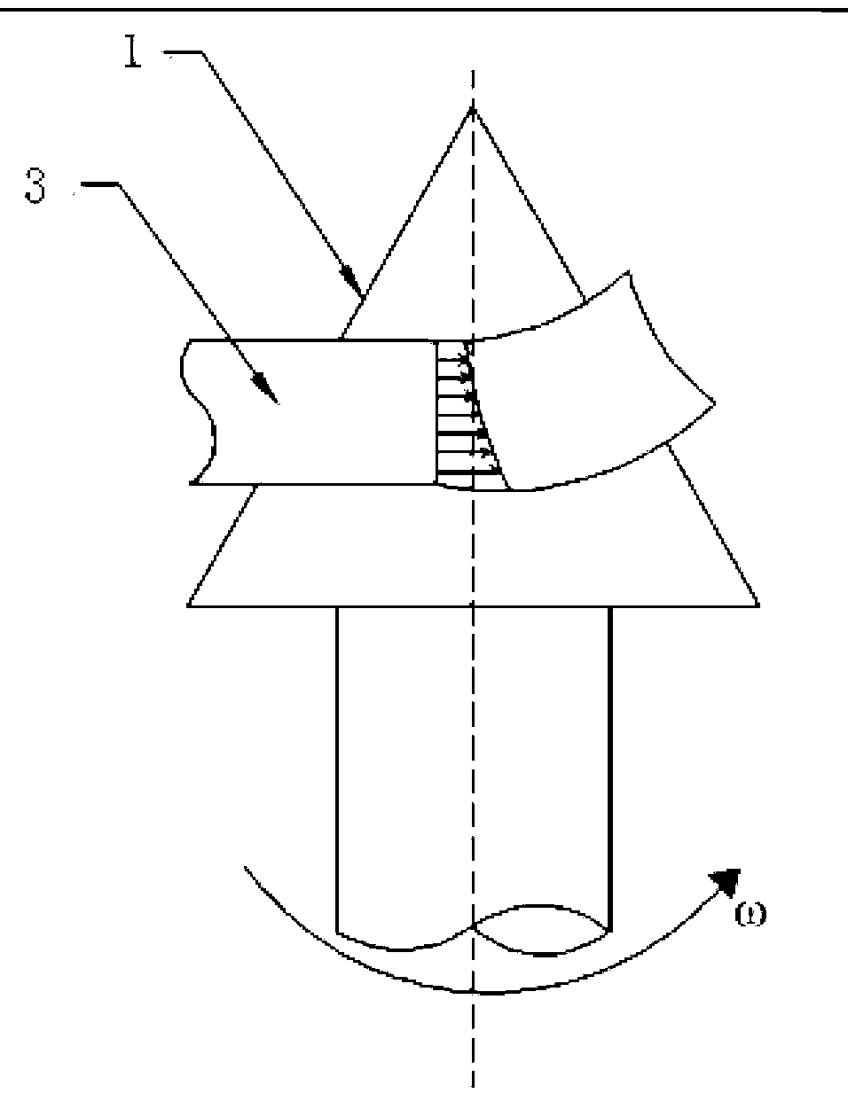
[0034] This embodiment is a method for continuously forming an in-plane bending ring piece with a thickness of the plate and strip realized on the roll adjustment mechanism of the in-plane bending forming device for the strip. The technical solution of the roll adjustment mechanism of the in-plane bending forming device for the strip is disclosed in the invention patent No. 200810231900.1. In this embodiment, the strip in-plane bending forming device includes a first roller and a second roller, and the two rollers are tapered rollers. The cone angles of the first roller and the second roller are α=60°, each Length of bus bar of roll l 0 =110mm. The first roll and the second roll are arranged symmetrically, and the angle between the axes of the two rolls is 60°. The thickness of the in-plane curved ring to be formed is t=1mm. The specific forming process is as follows:

[0035] Step 1. Prepare the sheet

[0036] According to the shape and size of the roll of the strip in-plane b...

Embodiment 2

[0055] This embodiment is a method for continuously forming an in-plane bending ring piece with a thickness of the plate and strip realized on the roll adjustment mechanism of the in-plane bending forming device for the strip. The technical solution of the roll adjustment mechanism of the in-plane bending forming device for the strip is disclosed in the invention patent No. 200810231900.1. In this embodiment, the strip in-plane bending forming device includes a first roller and a second roller, and the two rollers are tapered rollers. The cone angles of the first roller and the second roller are α=60°, each Length of bus bar of roll l 0 =110mm. The first roll and the second roll are arranged symmetrically, and the angle between the axes of the two rolls is 60°. The thickness of the in-plane curved ring piece to be formed is t=1.2mm. The specific forming process is as follows:

[0056] Step 1. Prepare the sheet

[0057] According to the shape and size of the roll of the strip in...

Embodiment 3

[0076] This embodiment is a method for continuously forming an in-plane bending ring piece with a thickness of the plate and strip realized on the roll adjustment mechanism of the in-plane bending forming device for the strip. The technical solution of the roll adjustment mechanism of the in-plane bending forming device for the strip is disclosed in the invention patent No. 200810231900.1. In this embodiment, the strip in-plane bending forming device includes a first roller and a second roller, and the two rollers are tapered rollers. The cone angles of the first roller and the second roller are α=60°, each Length of bus bar of roll l 0 =110mm. The first roll and the second roll are arranged symmetrically, and the angle between the axes of the two rolls is 60°. The thickness of the in-plane curved ring piece to be formed is t=1.4mm. The specific forming process is as follows:

[0077] Step 1. Prepare the sheet

[0078] According to the shape and size of the rolls of the strip i...


PUM


Abstract

An equal-thickness in-plane continuous plate strip bending method comprises the following steps: putting a plate strip into a roll gap determined between roll surfaces of two rolls; and positioning the lower surface of the plate strip at a point A, wherein the two rolls rotate synchronously face to face; the rotation speeds omega of the rolls are 2-10rad/s; at the beginning of forming, the plate strip has plastic deformation; since the linear velocities of the roll surfaces of the rolls have different distributions, the flow velocities of metal particles in the width direction of the plate strip in a deformed zone are in monotonous and uneven distribution; because of the distribution difference of the metal flow velocities, monotonous and uneven elongation deformation is generated in the length direction of the plate strip in the deformed zone; and due to coordinative development of the uneven elongation deformation, the plate strip develops in a direction forming a ring so as to be formed as an equal-thickness in-plane bent annular component. By the equal-thickness in-plane continuous plate strip bending method, during plastic bending, cracks in the outer zone of the bent component and wrinkles in the inner zone of the bent component caused by tension in the outer zone of the plate strip material and pressure in the inner zone of the plate strip material can be effectively avoided; and in the rolling process, the plate strip material is subject to work hardening, so that the mechanical properties of the plate strip material are improved.

Description

Technical field [0001] The invention relates to the field of plastic processing, and is a method for in-plane bending and forming of continuous plates and strips with equal thickness. Background technique [0002] Strip in-plane bending technology has a wide range of applications in plastic processing fields such as lightweight flange products, profile bending parts, and ring parts. During the forming process, the material presents a three-dimensional compressive stress state in the deformation zone, which is conducive to the plasticity of the metal material, can fully tap the forming potential of the material, and the forming limit of the material is greatly improved. At present, the traditional plastic bending method and blanking method are used for the manufacture of in-plane bending parts of the strip. The stress state of the outer zone of plastic bending and the inner zone of the inner zone is easy to cause the outer zone of the bending part to crack and the inner zone to w...

Claims


Application Information

Patent Timeline
IPC IPC(8): B21H1/06
Inventor 李宏伟冯璐杨合李智军李云海
Owner NORTHWESTERN POLYTECHNICAL UNIV
Why Eureka
Try Eureka