
Calibration method and calibration system for robot

A calibration method and robot technology, applied in the field of robot calibration and calibration system, can solve problems such as increasing cost

Inactive Publication Date: 2013-09-18
JTEKT CORP
View PDF7 Cites 8 Cited by
  • Summary
  • Abstract
  • Description
  • Claims
  • Application Information

AI Technical Summary

Problems solved by technology

[0005] JP8-27241A to Japanese Patent Publication No. 4-45842 require a hand-held camera, a three-dimensional measuring device or a displacement detector, so it will increase the cost

Method used


Image

  • Calibration method and calibration system for robot
  • Calibration method and calibration system for robot
  • Calibration method and calibration system for robot

Examples


Embodiment Construction

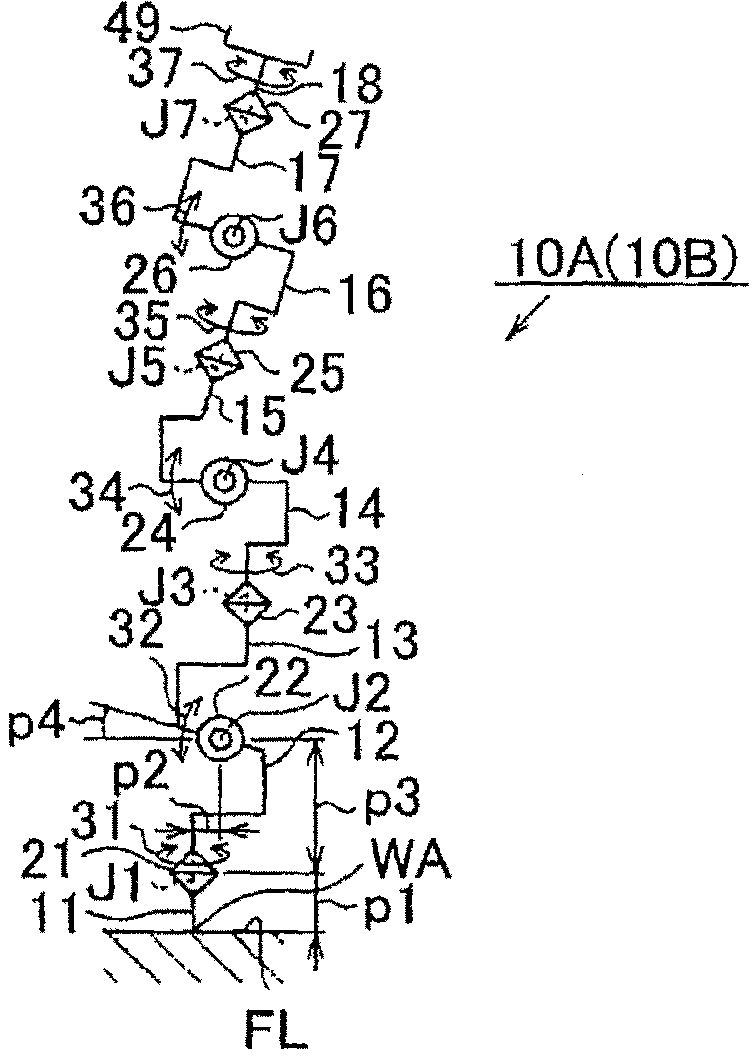
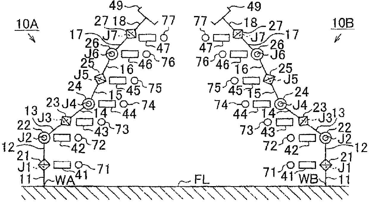
[0017] In the following, reference will be made to Figure 1 to Figure 5 A calibration method and a calibration system for a robot according to an exemplary embodiment of the present invention will be described. First, a pair of manipulators 10A and 10B according to the present embodiment will be described. The manipulator 10A and the manipulator 10B are placed within a range capable of coupling both ends of the manipulator 10A and the manipulator 10B to each other. In this embodiment, both the manipulator 10A and the manipulator 10B have the same components, so only the manipulator 10A will be described. The parts of the manipulator 10B are denoted with the same reference numerals as those of the parts of the manipulator 10A, and descriptions thereof are omitted.

[0018] Such as figure 1 As shown, the manipulator 10A is formed by serially coupling eight links 11 to 18 through seven joints 21 to 27 . The manipulator 10A as an articulated robot is a robot having 7 degrees ...


PUM


Abstract

A pair of manipulators (10A, 10B) are caused to take a plurality of attitudes in a state where distal ends of the manipulators (10A, 10B) are coupled to each other, coordinates of joints between links at each attitude change are acquired on the basis of detection signals, at each attitude change, of rotary encoders provided for servomotors that drive the links of the manipulators (10A, 10B), and a position and attitude of an installation point (WB) of a slave robot with reference to an installation point (WA) of a master robot are calculated on the basis of the joint coordinates acquired at the corresponding attitude change in a forward kinematics manner. A deviation vector for each attitude change between actual measured values of the installation point (WB) of the slave robot and the calculated values of the installation point (WB) of the slave robot is calculated, and robot constants of both manipulators are identified from the deviation vector.

Description

technical field [0001] The invention relates to a calibration method and a calibration system for a robot. Background technique [0002] Known methods for calibrating mechanical parameters of robots include methods described in Japanese Patent Application Publication No. 8-27241 (JP8-27241A), Japanese Patent Application Publication No. 2001-50741 (JP2001-50741A) and the like. In JP8-27241A, the robot is calibrated by simultaneously calibrating the hand-held camera and the robot. [0003] In JP2001-50741A, the end of the three-dimensional measuring device is coupled to the end of the arm of the robot, the position and attitude of the end portion of the arm of the robot are measured, and multiple measurements are made while changing the position and attitude of the robot. a teaching point. By doing so, the mechanical parameters of the robot (also known as robot constants) are obtained, and calibration is performed. [0004] Japanese Patent Publication No. 4-45842 describes ...

Claims


Application Information

Patent Timeline
Patent Type & Authority Applications(China)
IPC IPC(8): B25J3/00G01B21/00G01B21/04B25J19/00
CPCB25J9/1692G05B2219/39049B25J9/1682G05B2219/39048G05B2219/39051Y10S901/02B25J9/1674
Inventor 太田浩充向井康晴沼崎和也
Owner JTEKT CORP
Learn More