Eureka AIR delivers breakthrough ideas for toughest innovation challenges, trusted by R&D personnel around the world.

Forming mold and forming method of micro composite plastic part

A technology for forming molds and plastic parts, applied in the direction of coating, etc., can solve the problems of difficult finishing, complex precise assembly of different tiny components, and high cost

Active Publication Date: 2013-09-18
BEIJING UNIV OF CHEM TECH
View PDF5 Cites 1 Cited by
  • Summary
  • Abstract
  • Description
  • Claims
  • Application Information

AI Technical Summary

Problems solved by technology

Due to the miniaturization of components, traditional mechanical finishing is very difficult, and the precise assembly of different tiny components is also a complicated process, especially for precision micro-composite devices with irregular shapes and different materials, it is difficult to use this method to achieve
Therefore, in recent years, the micro-plastic molding technology using molds has been developed, which is a high-quality, high-precision processing and molding method, but at present this technology is mainly used for single parts or multi-part molding of the same type of material, and it is dedicated to special molds. higher cost
At present, there is no injection mold and molding method that can be integrally molded, multi-purpose, and precisely metered and controlled for micro-composite plastic parts containing rigid components and flexible components.

Method used


Image

  • Forming mold and forming method of micro composite plastic part
  • Forming mold and forming method of micro composite plastic part
  • Forming mold and forming method of micro composite plastic part

Examples


Embodiment approach

[0023] The second object of the present invention is to provide a molding method for injection molding micro-composite products using the above-mentioned molding mold, which can realize injection molding by hand or by an injection molding machine. A preferred embodiment is:

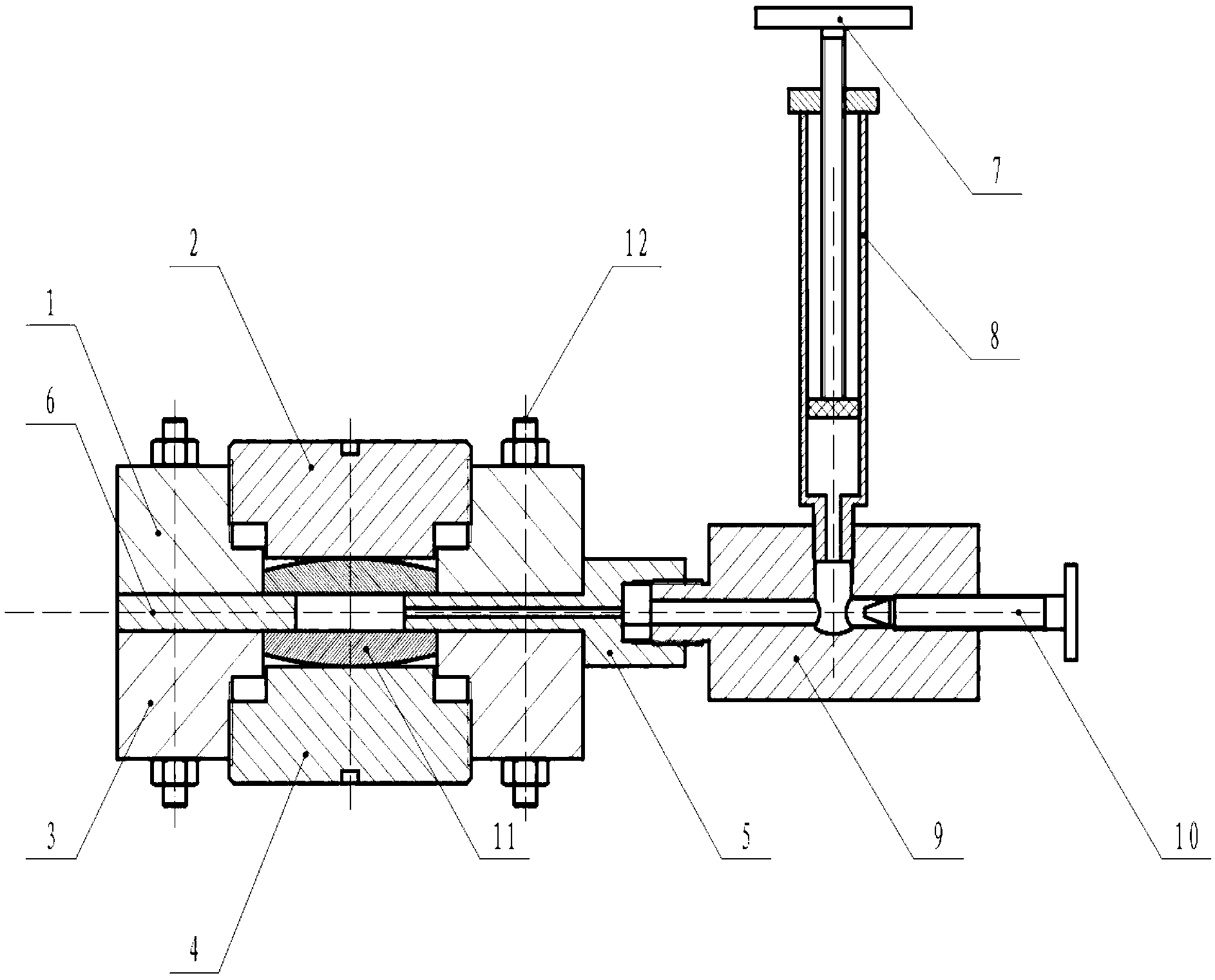
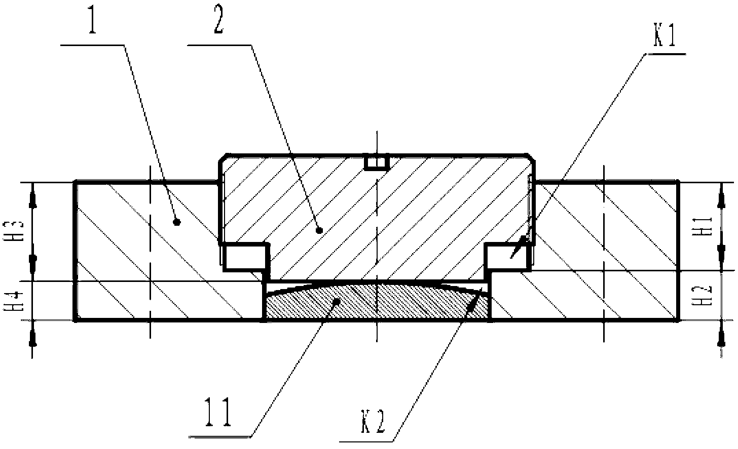
[0024] 1) Preload the rigid member 11 of the miniature composite plastic part into a specific position of the mold cavity, such as the installation hole of the upper and lower templates, adjust the position of the rigid member by changing the height of the threaded adjustment block screwed into the threaded hole, and place the upper mold , the middle mold, the lower mold part and the injection molding system are assembled separately, and the mold is closed;

[0025] 2) Unscrew the closed valve 10 to a suitable position, accurately measure and inhale and inject the flexible material into the runner cavity through the injection molding piston 7 and the barrel 8, and enter the mold cavity to fill it up, and ...


PUM


Abstract

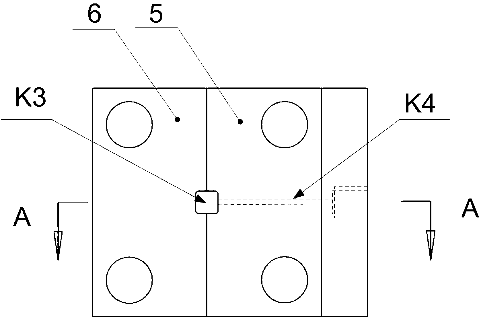
The invention discloses a forming mold and a forming method of a micro composite plastic part, belonging to the field of injection molds and forming. The mold comprises an upper mold, a middle mold, a lower mold and an injection molding system, wherein a forming cavity is formed by the upper mold, the middle mold and the lower mold; a rigid member is embedded into the forming cavity and then a flexible member is formed in an injection molding mode, so as to obtain the micro composite plastic part with the rigid member and the flexible member; a through hole formed by a threaded hole and a mounting hole is formed in each of the centers of upper and lower mold plates of the upper and lower molds; a thread adjusting block is arranged into the threaded hole; the rigid member is embedded into the mounting hole; the middle mold part is formed by two middle mold plates the centers of which are provided with symmetric forming cavity through holes; one of the middle mold plates is provided with a flowing channel hole and is connected with the injection molding system; the upper mold, the middle mold and the lower mold are connected to form a whole body through fixing bolts; the injection molding system comprises an injection molding piston with scales, a transparent cylinder with scales, an injection molding flowing channel cylinder and a sealing valve. The forming mold is compact in structure, the integral forming of the rigid member and the flexible member is realized, materials are precisely measured and fed, and one multipurpose mold is achieved.

Description

technical field [0001] The invention belongs to the technical field of injection molds and molding, and relates to an injection mold and a molding method for miniature composite plastic parts including rigid components and flexible components. Background technique [0002] For micro-composite devices, the traditional method is to process rigid components by mechanical finishing, and then use mechanical assembly or bonding to form. Due to the miniaturization of components, traditional mechanical finishing is very difficult, and the precise assembly of different tiny components is also a complicated process, especially for precision micro-composite devices with irregular shapes and different materials, it is difficult to use this method to achieve . Therefore, in recent years, the micro-plastic molding technology using molds has been developed, which is a high-quality, high-precision processing and molding method, but at present this technology is mainly used for single parts...

Claims


Application Information

Patent Timeline
IPC IPC(8): B29C45/14B29C45/36B29C45/60B29C45/62
Inventor 张立群姜秀娟伍社毛石锐陈大福林祥
Owner BEIJING UNIV OF CHEM TECH
Why Eureka
Eureka Blog
Learn More