Railway fastener self-adaptive positioning method based on image sequence and high-speed detection system

An image sequence and railway fastener technology, which is applied to railway car body parts, railway vehicle shape measuring devices, railway auxiliary equipment, etc., can solve problems such as automatic positioning of railway fasteners, to ensure integrity, reduce heat, and ensure reliability sexual effect

Active Publication Date: 2013-09-18
SHANGHAI JIAO TONG UNIV
View PDF6 Cites 10 Cited by
  • Summary
  • Abstract
  • Description
  • Claims
  • Application Information

AI Technical Summary

Problems solved by technology

[0007] In order to solve the problem of automatic positioning of existing railway fasteners, the present invention

Method used


Image

  • Railway fastener self-adaptive positioning method based on image sequence and high-speed detection system
  • Railway fastener self-adaptive positioning method based on image sequence and high-speed detection system
  • Railway fastener self-adaptive positioning method based on image sequence and high-speed detection system

Examples


Example Embodiment

[0033] Example 1

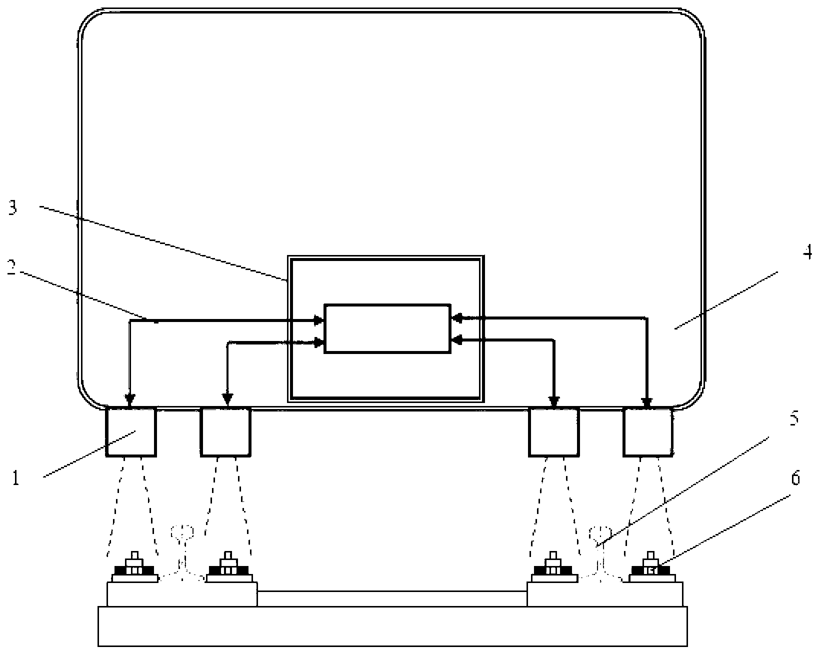
[0034] figure 1 It is a schematic diagram of the composition principle of a railway fastener high-speed detection system according to an embodiment of the present invention. The detection system of the present invention consists of three parts: the detector 1, the cable 2 and the controller 3. There are 4 detectors 1 in total, all of which are installed under the train carriage 4, directly above the area where the fasteners 6 on both sides of the two rails 5 are located. The controller 3 is installed in the carriage 4 and is connected to the four detectors 1 through the cable 2. During the operation of the train, the detector 1 continuously works and obtains real-time images of the area where the fastener 6 is located, and transmits it to the controller 3 through the cable 2, and automatically determines the automatic positioning of the fastener 6 through image processing and pattern recognition.

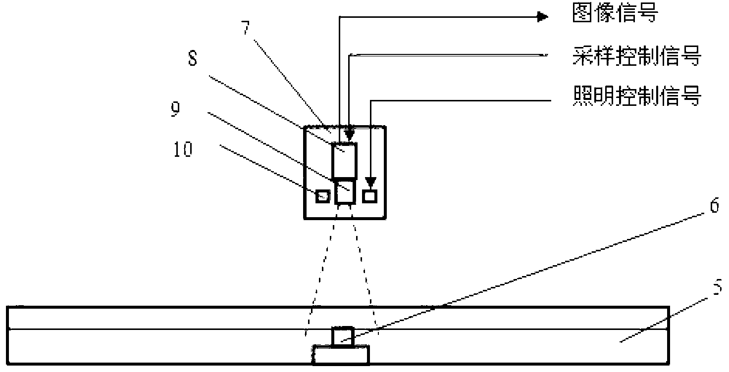
[0035] figure 2 It is a schematic diagram of the composition p...

Example Embodiment

[0043] Example 2

[0044] This embodiment relates to an adaptive positioning method for railway fasteners using the system of Embodiment 1. The method includes the following steps:

[0045] (1) After the stabilized power supply of the controller 3 is turned on, the computer 11 in the controller 3 and the camera 8 in the detector 1 start to be powered on.

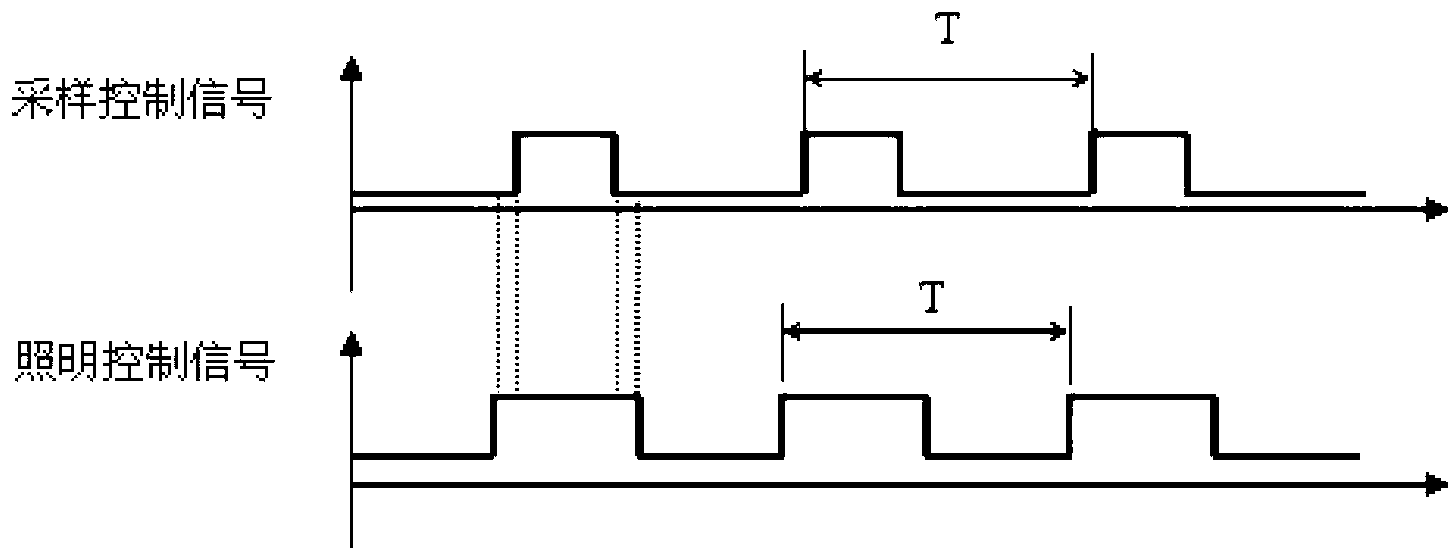
[0046] (2) The computer 11 in the controller 3 sends a sampling control signal and a lighting control signal to the camera 8 and the light source 10 in the detector 3 at a relatively high fixed frequency. The sampling frequency is generally the maximum frequency of the fastener. More than 2 times. For example, for a train running speed of 400km / h, a sleeper distance of 0.6m, and the frequency of corresponding fasteners up to about 185Hz, the sampling frequency may be 400Hz. The lighting control signal arrives earlier than the sampling control signal and ends later than the sampling control signal. After the camera 8 in the detec...


PUM


Abstract

The invention provides a railway fastener self-adaptive positioning method based on an image sequence and a high-speed detection system. The system consists of detectors, a cable and a controller, wherein four detectors are arranged below train carriages, and are over against the upper sides of regions where fasteners on both sides of two steel rails are positioned respectively; a controller is arranged in a carriage, and is connected with the four detectors through the cable; in the running process of a train, the detectors work continuously and are used for acquiring images of regions where the fasteners are positioned and transmitting to the controller via the cable; the controller is used for automatically adjusting the sampling frequency of a camera according to the appearance frequencies of the fasteners in the acquired image sequence and the positions of the fasteners in a visual field through image processing and mode identification, so that self-adaptive positioning and detection of the fasteners are realized.

Description

technical field [0001] The invention relates to equipment in the field of railway infrastructure detection, in particular to an image sequence-based adaptive positioning method for railway fasteners and a high-speed detection system thereof. Background technique [0002] As a major project related to the national economy and the people's livelihood, the safety and maintenance of railway is very important. With the increase of railway mileage and the increase of train speed, the demand for monitoring the status of railway infrastructure has risen rapidly. Fasteners are one of the most critical facilities in railway infrastructure, and the absence of fasteners will have a decisive impact on traffic safety. Traditional manual inspection and maintenance can no longer meet the requirements, so various track inspection equipment came into being. At present, the detection methods of railway fasteners are mainly divided into the following three types: [0003] The first is manual...

Claims


Application Information

Patent Timeline
IPC IPC(8): B61K9/08
Inventor 赵辉陶卫雷华明吴芳颜发才曾新贵
Owner SHANGHAI JIAO TONG UNIV
Why Eureka
Try Eureka