Rigid frame pile supporting and blocking structure

A technology of retaining structure and rigid frame, which is applied in the direction of foundation structure engineering, excavation, construction, etc., can solve the problems of large pile section size, large external pile length, affecting structural safety, etc., achieve reasonable internal force distribution, reduce pile length, The effect of excellent structural rationality

Inactive Publication Date: 2013-09-18
CHINA RAILWAY SIYUAN SURVEY & DESIGN GRP
View PDF5 Cites 5 Cited by
  • Summary
  • Abstract
  • Description
  • Claims
  • Application Information

AI Technical Summary

Problems solved by technology

However, the earth pressure or sliding force in the high fill section of the steep slope is huge, and there are still some problems in the above-mentioned retaining structure: when the cantilever end of the anti-slide pile is greater than 8m, the bending moment of the structure increases rapidly, resulting in a large section size of the pile and a high structural reinforcement ratio The h-shaped pile adopts a reinforced concrete structure, the beam is under compression, and the structural safety and durability are good, but there are shortcomings such as large length of the outer pile and large length of the hanging wall above the beam. The prior art generally improves the connection point between the beam and the pile However, the external piles and beams will be exposed to the ground, which will affect the appearance of the structure; anchor retaining walls, anchor piles, etc. use steel bars and steel hinges to resist horizontal forces, although the tensile strength of steel is fully utilized. , but because the engineering design life is generally greater than 50 years, under the influence of many factors such as air, groundwater and temperature changes, the steel is prone to rust, especially the end position connected with the concrete structure, and even affects the safety of the structure

Method used


Image

  • Rigid frame pile supporting and blocking structure
  • Rigid frame pile supporting and blocking structure

Examples


Embodiment Construction

[0015] The present invention will be further described below with reference to accompanying drawing of specification sheet and specific embodiment:

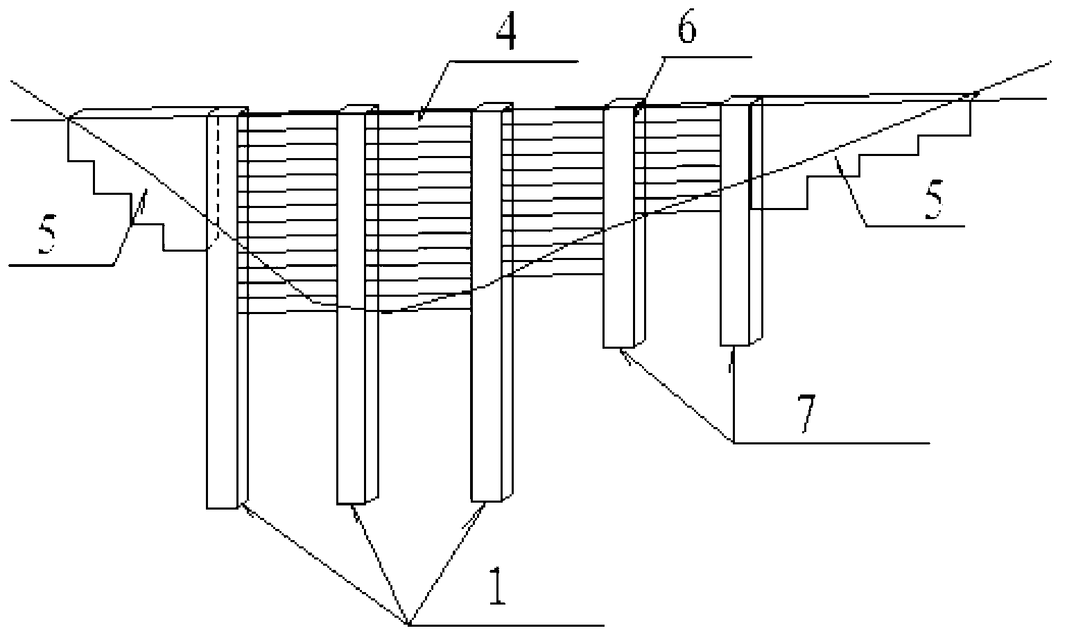
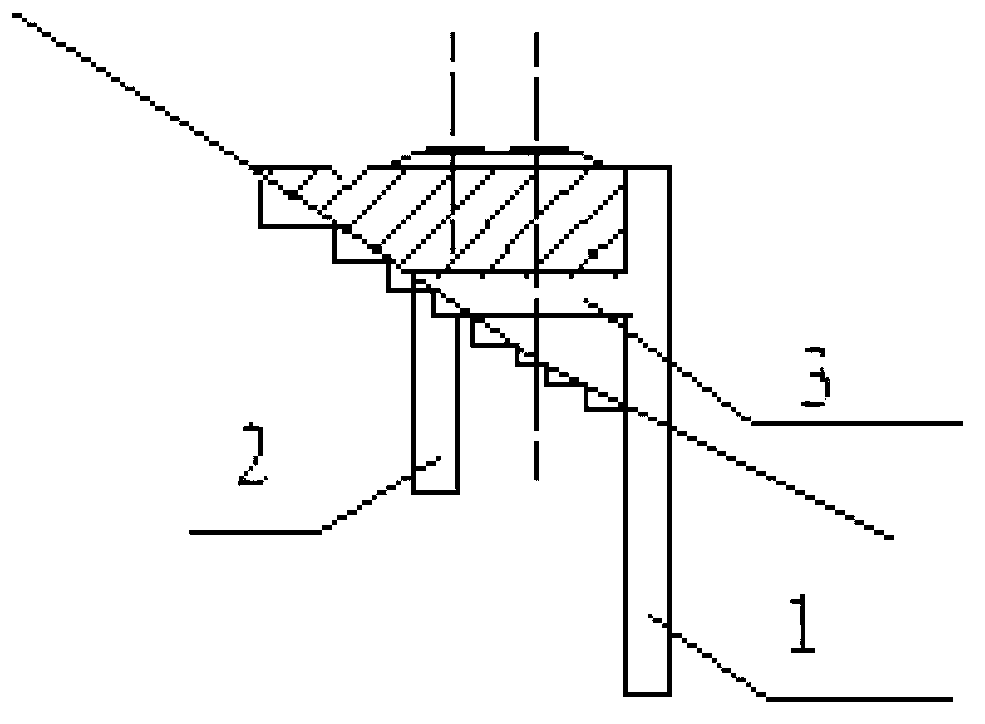
[0016] The invention provides a rigid frame pile support structure, which includes a plurality of h-shaped piles arranged at intervals in the transverse direction. The h-shaped piles include an outer anchor pile 1, an inner anchor pile 2 and a beam 3, the pile top of the inner anchor pile 2 and The pile bodies of the outer anchor piles 1 are connected by a beam 3, and the adjacent outer anchor piles 1 are connected by a retaining plate 4, and the outer anchor piles 1 pass through the rock and soil and are anchored in a stable foundation, and the inner anchor piles 2 and the beams 3 are both Embedded in the rock and soil body, the outer anchor pile 1 is arranged on the outer side of the steep slope, and the inner anchor pile 2 is arranged on the inner side of the steep slope. The soil retaining plate 4 is arranged on the inner sid...


PUM


Abstract

The invention relates to the construction field of abrupt slope square sections and provides a rigid frame pile supporting and blocking structure which comprises a plurality of h-type piles distributed parallelly, wherein each h-type pile comprises an outer anchoring pile, an inner anchoring pile and a beam, the pile tops of the inner anchoring piles and the pile bodies of the outer anchoring piles are connected through the beams, adjacent outer anchoring piles are connected through earth blocking plates, the outer anchoring piles penetrate a rock-soil body to be anchored in a stable foundation, the inner anchoring piles and the beams are all embedded in the rock-soil body, the outer anchoring piles are arranged on the outer side of an abrupt slope, and the inner anchoring piles are arranged on the inner side of the abrupt slope. The rigid frame pile supporting and blocking structure optimizes the existing h-type pile design, has high rigidity and good horizontal resistance, can bear high soil pressure or sliding force on highfill sections of the abrupt slope, has high safety and reliability and effectively solves the problem of difficult supporting of highfills of the abrupt slope.

Description

technical field [0001] The invention relates to the engineering construction field of railways, highways and other high fill sections with steep slopes, in particular to a rigid frame pile support structure for high fill sections with steep slopes. Background technique [0002] In the construction of railways, highways, field pads and other projects in mountainous areas, it is difficult to avoid steep slopes and high fill subgrades due to factors such as terrain, line type, stations, and ground attachments. Under the action of load, precipitation and other factors, the steep slope subgrade is prone to slide and damage along the slope. In order to ensure the stability of the steep slope subgrade, anti-slide piles, anchor piles, h-shaped piles, anchor retaining walls and other supporting structures are often used to reinforce the outside of the fill during construction. However, the earth pressure or sliding force in the high fill section of the steep slope is huge, and there...

Claims


Application Information

Patent Timeline
Patent Type & Authority Applications(China)
IPC IPC(8): E02D17/20
Inventor 韦随庆周青爽张占荣姚洪锡高威赵勇黄红华赵德文孟祥龙顾成权黄福海王亮刘洋
Owner CHINA RAILWAY SIYUAN SURVEY & DESIGN GRP
Why Eureka
Try Eureka