Air distribution mechanism for engine

A technology of valve train and engine, applied in engine components, machines/engines, mechanical equipment, etc., can solve problems such as insufficient air intake, and achieve the effect of low manufacturing cost

Inactive Publication Date: 2013-09-18
程钰
View PDF3 Cites 2 Cited by
  • Summary
  • Abstract
  • Description
  • Claims
  • Application Information

AI Technical Summary

Problems solved by technology

[0003] In order to overcome the problem of insufficient air intake of the existing valve mechanism at various speeds, the present invention provides a valve mechanism, which not only has the functions of steplessly variable

Method used


Image

  • Air distribution mechanism for engine
  • Air distribution mechanism for engine

Examples


Embodiment Construction

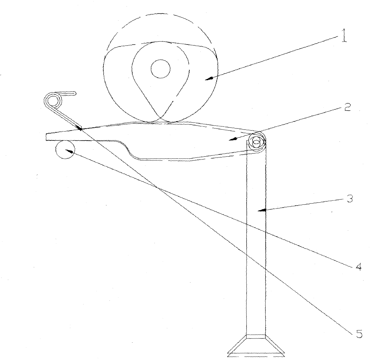
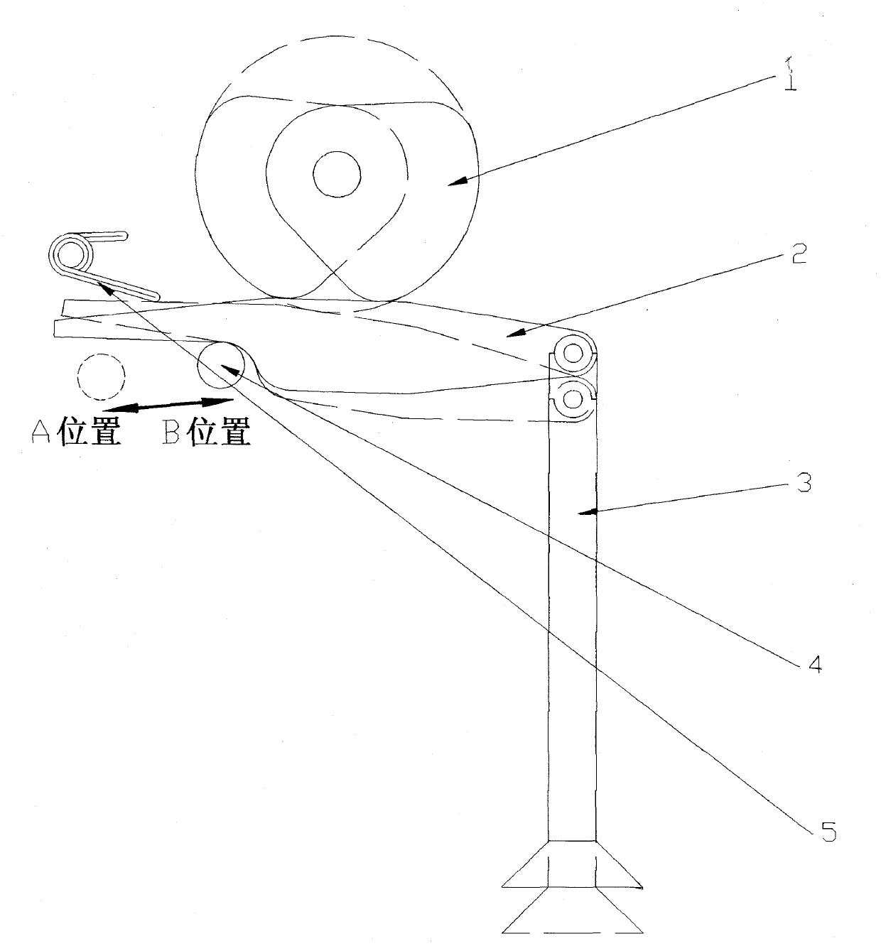
[0010] exist figure 1 In the shown embodiment, the sector cam (1), rocker arm (2), valve (3), rocker fulcrum (4), and return spring (5) are installed in sequence, and the valve (3), rocker fulcrum (4), return The bit spring (5) is installed on the engine cylinder head, and the rocking arm (2) is movably connected with the valve (3). One end of the return spring (5) presses the rocking arm to ensure that the rocking arm (2) is not separated from the rocking arm fulcrum (4) during work. The rocking arm fulcrum (4) can slide by the design track on the cylinder head. The fulcrum of the rocker arm is on the far left, and the valve stroke and valve opening angle are at the minimum state.

[0011] When the position of the fulcrum (4) of the rocker arm remains unchanged, the fan-shaped cam (1) rotates clockwise under the drive of the main shaft of the engine. When the fan-shaped cam (1) contacts the rocker arm (2), the rocker arm (2) rotates The rocker arm fulcrum (4) rotates back ...


PUM


Abstract

The invention discloses an air distribution mechanism capable of changing z valve timing and valve stroke. A sector cam (1) rotates clockwise under the drive of a main shaft of the engine; and when the sector cam (1) is contacted with a rocker arm (2), the rocker arm (2) rotates around a rocker arm pivot (4), and a valve (3) is regularly opened and closed under the drive of the rocker arm (2). When the sector cam (1) and the rocker arm (2) are separated, the valve is completely closed under the action of a valve return spring. The rocker arm pivot (4) moves to the sector cam (1) along a rail under the action of external force, the distance between the rocker arm (2) and the sector cam (1) becomes small, and the sector arm (1) and the rocker arm (2) can be contacted in advance and delayed to separate in the rotating process. Therefore, the aim that the advanced opened angle and the delayed closed angle of the valve are increased is fulfilled; and according to a lever principle, the valve stroke can be increased along with the change of the position of the rocker arm pivot (4).

Description

Technical field [0001] The invention relates to a gas distribution mechanism of an engine, which can change the engine valve timing and valve stroke steplessly and simultaneously. Background technique [0002] At present, the known engine valve train is mainly made up of cam, rocker arm, valve, ejector column and return spring. After the design is finalized, the timing of the valve is certain, and the maximum stroke of the valve is also certain. It is not conducive to the ideal intake effect of the engine at various speeds. With the development of engine technology, various variable valve timing technologies and variable valve stroke technologies have appeared on the engine. But only BMW has achieved the synchronization of valve timing and valve stroke through mechanical means and is a stepless change. BMW's structure adopts double rocker arms and double cams, and adjusts the angle of one cam to meet the requirements of variable valve timing and variable valve stroke. The...

Claims


Application Information

Patent Timeline
IPC IPC(8): F01L1/34F01L1/08F01L1/18
Inventor 程钰
Owner 程钰
Why Eureka
Try Eureka