
Design method for light source subsystem of light environment simulation device

A technology of light source subsystem and simulation device, which is applied to the parts of lighting device, lighting device, light source fixing, etc., and can solve the problems of poor uniformity of illumination and high equipment cost

Active Publication Date: 2015-04-29
AIR FORCE MEDICAL CENT PLA +1
View PDF4 Cites 0 Cited by
  • Summary
  • Abstract
  • Description
  • Claims
  • Application Information

AI Technical Summary

Problems solved by technology

[0005] The technical problem to be solved by the present invention is that the illuminance uniformity of the light environment simulation system in the prior art is poor, or the equipment cost is relatively high, and a light source of a light environment simulating device with low cost and high illuminance uniformity is provided layout design method

Method used


Image

  • Design method for light source subsystem of light environment simulation device
  • Design method for light source subsystem of light environment simulation device
  • Design method for light source subsystem of light environment simulation device

Examples


Embodiment Construction

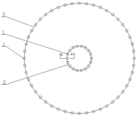
[0029] A design method for a light source subsystem of a light environment simulation device, used for designing a light source subsystem of a light environment simulation device that simulates a light environment in a simulated plane area, the light source subsystem of the light environment simulation device is a New product. The design method includes the following steps:

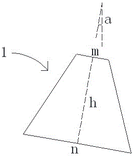
[0030] ①Select the light source arrangement method, and use several light source modules 1 to arrange in turn to form a circular inner light source circle 2 and an outer light source circle 3, the inner light source circle 2 and the outer light source circle 3 are arranged concentrically; the inner light source circle The optical axis of the light source module 1 on 2 is deflected outward along the radial direction of the inner light source ring 2, and the light source module 1 includes a light source and a lampshade 11, and the lampshade 11 is in the shape of a hollow truncated cone.

[0031] ② Select t...


PUM


Abstract

A design method for a light source subsystem of a light environment simulation device comprises the following steps: 1, selecting light source arrangement way, and sequentially arranging a plurality of light source modules to form a round internal light source ring and a round external light source ring which are concentric, wherein optical axes of the light source modules on the internal light source ring deflect outwards in the radial direction of the internal light source ring, and each light source module comprises a light source and a hollow lamp shade in the shape of a round platform; 2, calculating the diameter of the external light source ring through the area of a simulation plane surface; and 3, acquiring the diameter of the internal light source ring, the optical axis deflection angle of the light source modules on the internal light source ring and the size of the lamp shade through the intensity of the illumination uniformity of the simulated light environment in the simulation plane surface area, the distance between the light environment simulation device and the simulation plane surface area, and the diameter of the external light source ring. Therefore, the method provided by the invention is lower in cost and higher in illumination uniformity.

Description

technical field [0001] The invention relates to the technical field of photobiology experiment instruments, in particular to a design method of a light source subsystem of a light environment simulation device. Background technique [0002] With the development of computer technology and virtual reality technology, artificially simulated light environments are increasingly used in various experimental studies, especially the simulation of natural light environments, which are widely used in many disciplines such as architecture, physics, and medicine. There are a wide range of applications. Moreover, among many signal simulation technologies, the simulation of optical signals is the most complex, far more difficult than sound simulation, temperature simulation, electrical signal simulation, and force simulation. Research institutions have been working hard to solve the problem. [0003] In order to improve the uniformity of the illuminance of the simulated light environmen...

Claims


Application Information

Patent Timeline
Patent Type & Authority Patents(China)
IPC IPC(8): F21V19/00
Inventor 郭小朝熊端琴付威威刘敏章程国佳师国伟白玉杜健王嫣嫣王聪
Owner AIR FORCE MEDICAL CENT PLA
Learn More