Method for monitoring effective coverage of concrete vibration in real time

A coverage and real-time monitoring technology, applied in measurement devices, radio wave measurement systems, satellite radio beacon positioning systems, etc., can solve problems such as many dead spots in management, poor control effects, and large investment in human resources, and achieve simple implementation. , avoid errors, the effect of high data accuracy

Active Publication Date: 2013-09-18
POWERCHINA CHENGDU ENG
View PDF8 Cites 18 Cited by
  • Summary
  • Abstract
  • Description
  • Claims
  • Application Information

AI Technical Summary

Problems solved by technology

[0004] 1. It is difficult to monitor the vibrating position of the vibrating equipment in real time
[0005] 2. It is difficult to quickly and accurately judge the effectiveness of vibrating construction, that is, whether it can completely and effectively cover the entire construction vibrating operation area
[0006] 3. It is impossible to obtain and judge abnormal conditions such as construction leakage, under-vibration, and over-vibration in real time
[0007] 4. The current general construction monitoring method mainly adopts the manual management of supervisors, which requires a large investment in human resources, many management dead ends, and poor control effects. It is difficult to judge construction abnormalities in real time and accurately
[0008] 5. The vibration process cannot be recorded effectively in real time, and cannot provide construction process data for later quality assessment and operation and maintenance
[0009] 6. The operation or quality problems in the vibration process cannot be fed back to the operators and managers in time during the vibration process

Method used


Image

  • Method for monitoring effective coverage of concrete vibration in real time
  • Method for monitoring effective coverage of concrete vibration in real time
  • Method for monitoring effective coverage of concrete vibration in real time

Examples


Embodiment Construction

[0026] The method for real-time monitoring of effective coverage of concrete vibration in the present invention comprises:

[0027] In the system, the vibrating area is divided into regular virtual grid i according to the set interval, and the vibrating coefficient C of each grid is i initialized to 0;

[0028] The vibrating equipment is provided with a positioning device, and the coordinates (x, y) of the vibrating equipment are obtained in real time through the positioning device, so as to accurately locate the current position of the vibrating equipment. The positioning device includes GPS (Global Positioning System), Beidou satellite positioning device, UWB (Ultra Wide band) or Zigbee wireless positioning device;

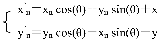
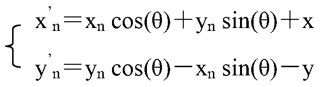
[0029] The azimuth angle θ of the vibration is obtained in real time through the azimuth angle sensing device installed on the vibrating equipment, combined with the acquired coordinates (x, y) of the vibrating equipment and the vibration shape data of the vibr...


PUM


Abstract

The invention relates to a method for monitoring the effective coverage of concrete vibration in real time, which includes the following steps: a vibrated area is divided into a regular virtual grid according to a set interval; the coordinates of vibrating equipment are acquired by a positioning device in real time; the azimuth of vibration is acquired by an azimuth sensing device in real time, and in combination with the coordinates of the vibrating equipment and vibrated shape data, the effective vibration-affected area of the vibrating equipment is calculated; the effective vibration-affected area is mapped into the virtual grid, and according to whether the effective vibration-affected area is completely covered by the virtual grid, the coverage coefficient of the virtual grid is calculated; and according to the coverage coefficient of the virtual grid, vibration data are statistically analyzed. The method realizes the automatic monitoring of the coverage of concrete vibration, dispensing with manual intervention, and moreover, the method realizes the real-time monitoring of the coverage of vibration, prevents the errors of artificial judgment, and ensures that the process of vibration is more intelligentized, the precision of data is high, and the method is stable and reliable.

Description

technical field [0001] The invention relates to the monitoring of the vibration quality of large-volume concrete pouring in the water conservancy and hydropower industry, in particular to a method for real-time monitoring of the effective coverage range of concrete vibration. Background technique [0002] Concrete vibration is the key process of concrete pouring, and the monitoring and control of vibration quality in the process is one of the important links of concrete quality control. Concrete vibration refers to vibrating and compacting the concrete mixture unloaded into the pouring bin to meet the design quality requirements. The traditional vibrating quality control on the construction site is to ensure the full coverage of the concrete pouring area through the staggered insertion of the vibrating rods, and at the same time control the insertion depth and angle of the vibrating rods, as well as the vibrating time and vibrating time through extensive empirical methods. ...

Claims


Application Information

Patent Timeline
Patent Type & Authority Applications(China)
IPC IPC(8): G01B21/00G01S19/39
Inventor 刘永亮刘金飞王仁坤尹习双宋述军钟桂良邱向东
Owner POWERCHINA CHENGDU ENG
Why Eureka
Try Eureka