Optical system internal chamber precision gas control method and device thereof

An optical system and internal chamber technology, applied in the direction of fluid pressure control without auxiliary power, etc., can solve the problems of inability to meet the requirements, poor adaptability of the optical system, etc., to suppress secondary pollution, simple structure, and good pressure stability. Effect

Active Publication Date: 2013-09-18
SHANGHAI MICRO ELECTRONICS EQUIP (GRP) CO LTD
View PDF5 Cites 8 Cited by
  • Summary
  • Abstract
  • Description
  • Claims
  • Application Information

AI Technical Summary

Problems solved by technology

[0012] Another purpose of the present invention is to provide a precision gas control method for the inner chamber of the optical system in view of defects such as the poor adaptability of the existing optical system and the inability to meet the requirements in the prior art

Method used


Image

  • Optical system internal chamber precision gas control method and device thereof
  • Optical system internal chamber precision gas control method and device thereof
  • Optical system internal chamber precision gas control method and device thereof

Examples


no. 1 approach

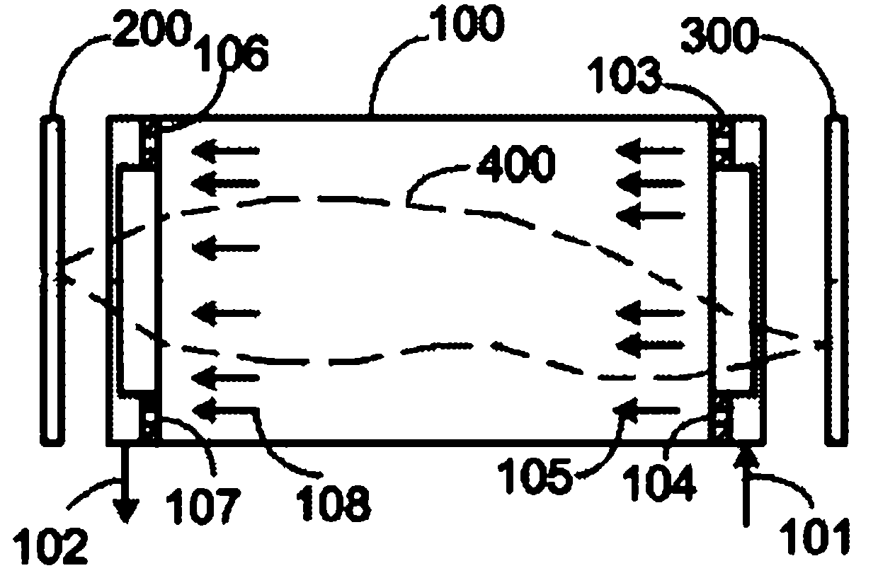
[0039] see figure 1 , figure 1 Shown is a schematic diagram of the structure of the imaging device and its internal chamber of the optical system. The imaging device includes an optical system 100 , and an object plane 200 and an image plane 300 respectively disposed on both sides of the optical system 100 . The light path 400 enters the optical system 100 after passing through the object plane 200 , and is projected onto the image plane 300 after being processed inside the optical system 100 . The inner chamber of the optical system 100 is filled with the cleaning gas, and the uniform flow of the gas can enhance the cleaning effect. In order to realize gas flow, an air inlet 101 and an air outlet 102 are respectively provided at both ends of the optical system 100 . In order to achieve the uniformity of the input air flow, an air intake flow equalization component 103 is provided in the inner chamber on the side of the air inlet 101 of the optical system 100 . The intak...

no. 2 approach

[0070] The difference between the second embodiment and the first embodiment is that the inner chamber of the optical system involved in the second embodiment requires absolute pressure control, and the first gas control circuit designed by the above method needs to be adjusted accordingly. The same numbers are used for the same parts of the second embodiment and the first embodiment, and the same parts will not be repeated.

[0071] see Figure 6 , Figure 6 Shown is a schematic diagram of the structure of the precise gas control device in the inner chamber of the optical system with the function of absolute pressure control. The precision gas control device in the inner chamber of the optical system with absolute pressure control function includes an optical system 100, a second gas control circuit 550 and a control system. The second gas control circuit 550 includes two parts: a gas supply circuit and an exhaust circuit. The gas supply circuit includes control devices an...


PUM


Abstract

The invention provides an optical system internal chamber precision gas control device. The device comprises an optical system and a gas control loop which is designed by adopting a control parameter decoupling method. An optical system internal chamber precision gas control method comprises a gas control loop control parameter decoupling method. The method specifically comprises the steps of giving a control parameter set; carrying out sensitivity analysis on the control parameter set; carrying out relative independence analysis on the control parameter set; carrying out first sectioning on control parameters; selecting a control device; judging the feasibility of the control device; if the control device is feasible, completing the building of the gas control loop; if the control device is not feasible, carrying out secondary sectioning; selecting a control device; judging the feasibility of the control device of each section; if the control device is feasible, completing the building of the gas control loop; and if the control device is not feasible, carrying out sectioning again until the control device is feasible. According to the invention, multi parameter decoupling can be carried out on the gas loop to realize high power depressurization; secondary pollution can be inhibited; the pressure stability is great; the parameters are adjustable online; and the method and the device have the advantages of simple structure, high reliability and convenient maintenance.

Description

technical field [0001] The invention relates to a gas pressure control device and method for adjusting and stabilizing input compressed gas at required pressure and flow rate, in particular to a precision gas control method and device for an inner chamber of an optical system. Background technique [0002] In optical lithography, the performance of the imaging optical system is a key factor in determining the size and uniformity of integrated circuit features. Under the requirements of smaller and more uniform feature sizes of integrated circuits, the structure of the optical system itself has become more and more complex. The internal and external environmental conditions of the system put forward more stringent requirements, including pollution, temperature, pressure, etc. [0003] The pollution control of the optical system is generally carried out by filling the inner chamber of the optical system with purified gas. Contamination of the optical system inside the optica...

Claims


Application Information

Patent Timeline
Patent Type & Authority Applications(China)
IPC IPC(8): G05D16/04
Inventor 聂宏飞杨志斌俞芸李其涛王云英
Owner SHANGHAI MICRO ELECTRONICS EQUIP (GRP) CO LTD
Why Eureka
Try Eureka