Converter tapping monitoring control system based on thermal image processing

An image processing, monitoring and control technology, applied in the manufacture of converters, etc., can solve the problems of difficult to guarantee recognition rate, unadjustable resolution, difficult reconstruction optimization, etc., to achieve timely and accurate alarm, increase system cohesion, and system parameters Online adjustable effects

Inactive Publication Date: 2012-07-04
杭州谱诚泰迪实业有限公司
3 Cites 6 Cited by

AI-Extracted Technical Summary

Problems solved by technology

In addition, the existing infrared slag detection system still has the following problems: the system architecture is unstructured, and it is difficult to reconstruct an...

Abstract

The invention relates to the field of automation control of ferrous metallurgy and aims at providing a converter tapping monitoring control system based on thermal image processing. The converter tapping monitoring control system comprises a far infrared data collecting module, an industrial field control unit, an industrial field auxiliary unit and a system control unit, wherein the far infrared data collecting module is connected with a far infrared thermal imaging instrument; the system control unit comprises a split mounting type indoor control cabinet; and functional devices such as an industrial grade liquid crystal display device, an industrial grade personal computer, an industrial field processing control unit, a power source management unit and an electrical control unit are integrated inside the split mounting type indoor control cabinet. For the converter tapping monitoring control system, the component-based module design and encapsulation are adopted, the system cohesion is increased, and the coupling between modules is reduced so that the converter tapping monitoring control system can be reconstructed according to different continuous casting production conditions and process requirements. The converter tapping monitoring control system is convenient to install and maintain and has no influence on steel-making production as the original equipment is not transformed; and the converter tapping monitoring control system has the advantages of non-contact type detection, automatic regulation of internal temperature, automatic dust removal, sealing protection of a metal housing and long service life.

Application Domain

Manufacturing converters

Technology Topic

Contact typeControl system +20

Image

  • Converter tapping monitoring control system based on thermal image processing
  • Converter tapping monitoring control system based on thermal image processing
  • Converter tapping monitoring control system based on thermal image processing

Examples

  • Experimental program(1)

Example Embodiment

[0033] With reference to the drawings, the present invention will be described in detail below.
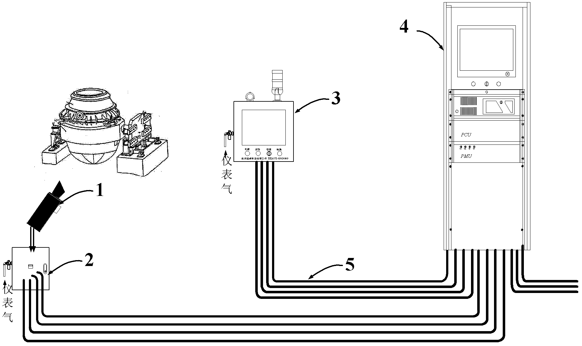
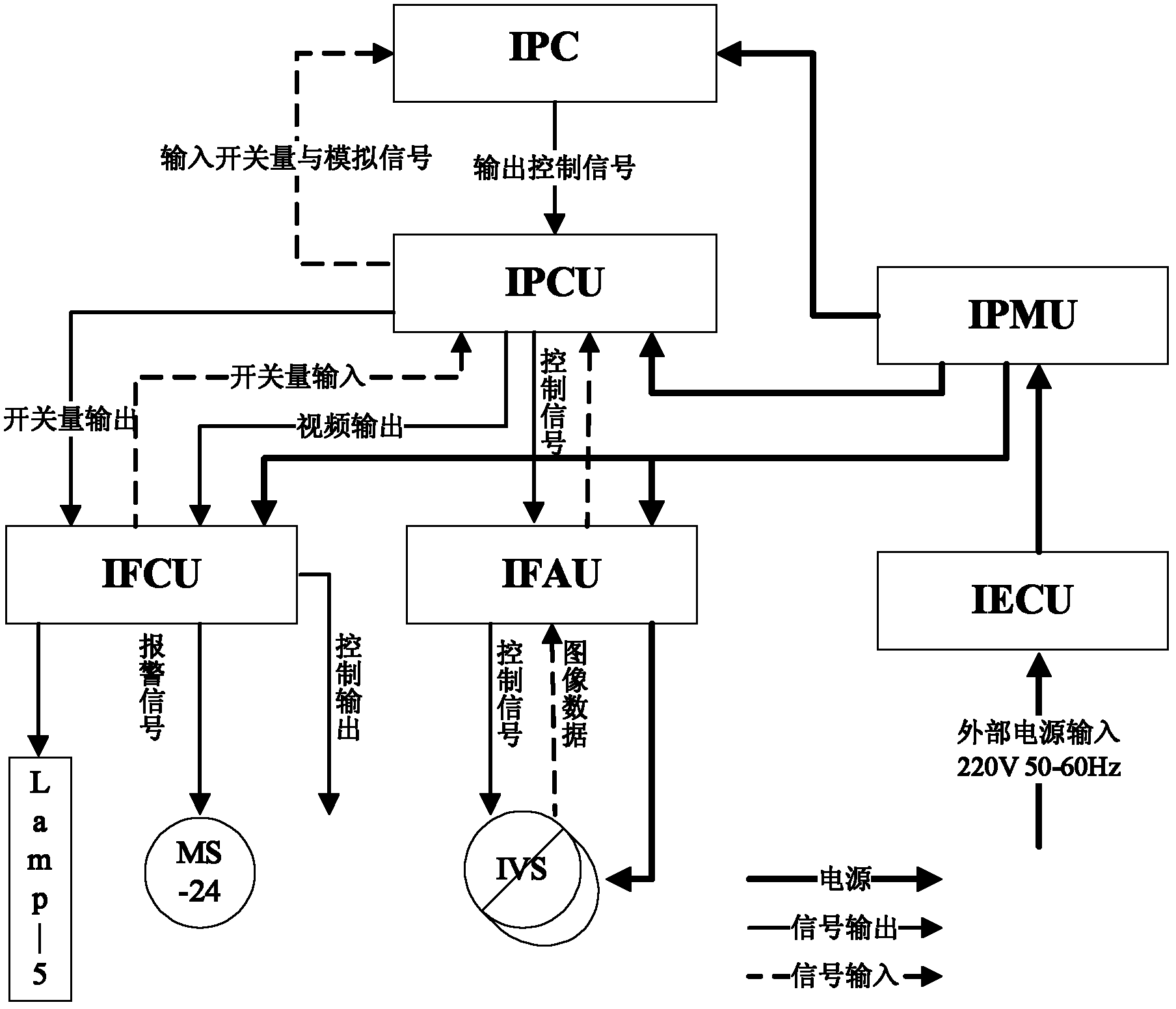
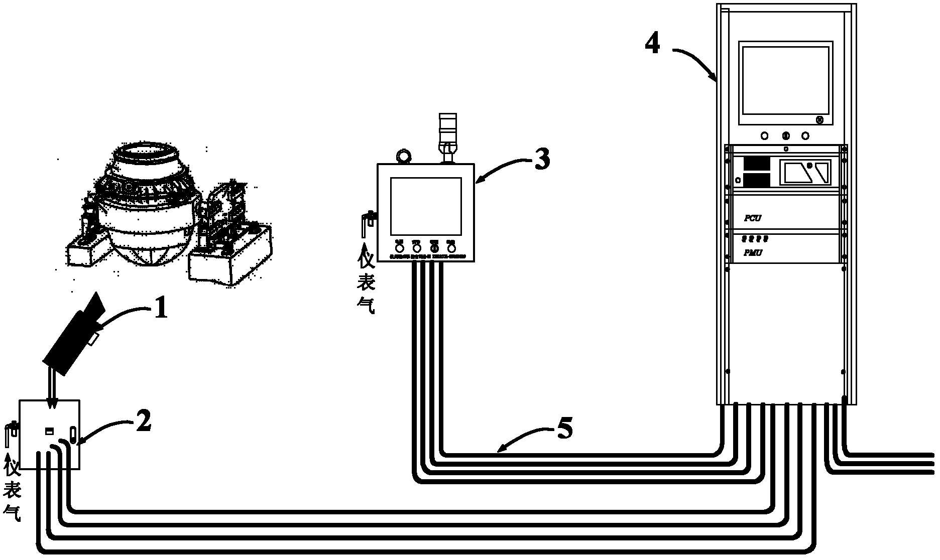
[0034] 1. System functional architecture and module composition
[0035] The overall technical scheme of the present invention is: using a far-infrared thermal imaging camera to collect the thermal image signal of the steel flow during the converter tapping, according to the difference in thermal emissivity of molten steel and steel slag contained in the steel flow in a specific far-infrared band, combined with discrete wavelet The Discrete Wavelet Transfer (DWT) algorithm is used to identify the state of the steel flow online, and then issue relevant control instructions to drive the on-site execution device to complete the real-time monitoring and automatic control of the converter tapping, and ultimately reduce the slag in the ladle The purpose of improving the yield of molten steel and reducing the labor intensity of workers.
[0036] The functional architecture of the system consists of the system control unit (Industrial Monitoring Control Unit, IMCU), the industrial field control unit (Industrial Field Control Unit, IFCU), the industrial field auxiliary unit (Industrial Field Associated Unit, IFAU), and the far-infrared data acquisition module (Infrared Video Sampling System, IVS) and other components.
[0037] The far-infrared data acquisition module (IVS) 1 integrates a temperature sensor, a coil heating device, a gas cooling device and a dust removal device; the above configuration can effectively maintain the relative stability of the ambient temperature of the infrared camera and reduce the interference of on-site dust on image quality . The far-infrared data acquisition module (IVS) 1 collects the steel flow image signal, temperature signal, converter inclination angle signal, oxygen lance height signal and the front and back shaking signal of the furnace body through the far-infrared thermal imaging camera. The signal is sent to the industrial field processing control unit, and after the digital signal preprocessing operation, it is output to the industrial-grade personal computer for calculation analysis, and the current steel flow state is obtained. The system control unit (IMCU) 4 converts the obtained steel flow status signal into system control instructions, and outputs it to the industrial field control unit (IFCU) 3 through the signal line, drives the alarm horn and the alarm lamp to work, and automatically controls the furnace to be raised and closed The tap slide plate.
[0038] The industrial field control unit (IFCU) 3 is the front-end control component of the system, and drives the execution device according to the instructions issued by the system control unit (IMCU) 4. It mainly completes the following functions: remote display of graphical user interface on site; control of on-site alarm devices, including Lamb-5 five-color warning light control and MS-24 slag alarm horn; for on-site operators to perform manual input detection and shutdown detection (system default It is automatic); it is for on-site operators to manually or automatically close the slide plate. The industrial field control unit (IFCU) 3 module, as the core component of field control, is connected with other modules on the field. Signals from the scene, such as far-infrared data acquisition module (IVS) 1 temperature, video signal, converter inclination, oxygen lance height, alarm level, automatic shutdown, etc. are sent to the industrial field control unit (IFCU) 3 module after pre-processing The industrial field processing control unit (IPCU) of the system control unit (IMCU) 4.
[0039] The main function of the Industrial Field Auxiliary Unit (IFAU) 2 is to serve the far-infrared data acquisition module (IVS) 1, providing it with power and cooling and heating gas sources, while receiving the system control unit (IMCU) 4 control commands to control the far-infrared data Startup, initialization, image acquisition of the acquisition module (IVS) 1, and the cooling, heating and dust removal operations of the far infrared data acquisition module (IVS) 1; working status of the far infrared data acquisition module (IVS) 1 (including ambient temperature and working mode) , Working parameters, etc.) are uploaded to the system control unit (IMCU) 4 of the converter control room control cabinet via the industrial field auxiliary unit (IFAU) 2.
[0040] The system control unit (IMCU) 4 is an assembled indoor control cabinet, and the metal material adopts high-quality cold plates after surface treatment to ensure good protection performance and strong corrosion resistance of the frame; the control cabinet is equipped with a grounding terminal at the bottom of the machine room The ground wire of the control cabinet can be directly connected to the ground terminal at the bottom of the control cabinet; the top of the control cabinet is equipped with a fan panel to ensure that the hot air in the control cabinet is smoothly discharged; the bottom of the control cabinet is equipped with a connection hole, which can provide power lines, signal lines and Control line connection.
[0041] The system control unit (IMCU) 4 is the functional core component of the system, and its installation location is the main control room of the metallurgical workshop, which completes the online judgment and automatic control of the converter tapping process; based on the above requirements, the internal system control unit (IMCU) 4 Integrates the following functional devices: Industrial Liquid Crystal Device (ILCD), Industrial Personal Computer (IPC), Industrial Processing Control Unit (IPCU), Power Management Unit (Industrial Industrial Power Management Unit, IPMU) and Electrical Control Unit (Industrial Electric Control Unit, IECU).
[0042] The Industrial Field Processing Control Unit (IPCU) accepts the real-time graphic image signal uploaded by the Industrial Field Auxiliary Unit (IFAU) 2, and completes three main tasks: preprocessing the input signal, outputting the control signal, and communicating with the industrial personal computer (IPC) . Among them, the signal preprocessing process is to preprocess the signals uploaded by the Industrial Field Control Unit (IFCU) 3 and Industrial Field Auxiliary Unit (IFAU) 2, as the discrete data source for online judgment of the steel flow state, which comes from the Industrial Field Control Unit ( The signals of IFCU)3 include: converter inclination angle signal, furnace body front/back shake signal, oxygen lance height signal, alarm level signal, field button signal; the signal from the industrial field auxiliary unit (IFAU) 2 includes far infrared data acquisition module (IVS)1 The temperature signal and video signal collected. The output control signals are control instructions respectively output to the industrial field control unit (IFCU) 3 and the industrial field auxiliary unit (IFAU) 2 to complete the automation operation of the converter tapping process. The control signals output to the industrial field control unit (IFCU) 3 include: steel stream video signal, detection status signal, alarm light signal, horn signal, reserved control signal; output to the industrial field auxiliary unit (IFAU) 2 control signal Including: camera start signal, dust removal signal, cooling signal, heating signal. The communication process with the industrial personal computer (IPC) refers to the steel flow status monitoring data uploaded by the industrial field processing control unit (IPCU) to the industrial personal computer (IPC), which mainly includes: steel flow video data, preprocessed inclination angle Data, preprocessed temperature data, preprocessed oxygen lance height data, preprocessed alarm level data, preprocessed switch control information.
[0043] The power management unit (IPMU) provides power for the system control unit (IMCU) 4 and the industrial field control unit (IFCU) 3. Its rated input AC 220V, 50~60HZ, rated input current <5A, and has power supply working/abnormal display function .
[0044] The electrical control unit (IECU) is used for system electrical control and cable 5 connection, including air switch, power fuse, panel control and circuit connectors.
[0045] 2. Module dependency and electrical connection
[0046] The module dependencies and electrical connections of the system are as attached figure 2 Shown. The Industrial Field Control Unit (IFCU) 3, as the core component of field control, is connected with other modules in the field. Signals from the scene, such as far infrared data acquisition module (IVS) 1 temperature, video signal, converter inclination, oxygen lance height, alarm level, automatic shutdown, etc. are pre-processed by the industrial field control unit (IFCU) 3 and sent to the system Industrial field processing control unit (IPCU) of the control unit (IMCU).
[0047] The industrial field processing control unit (IPCU) performs secondary processing on the signal from the field and uploads it to the data acquisition card of the industrial personal computer (IPC), and uses the discrete wavelet transform image analysis algorithm to perform comprehensive analysis and calculation on the collected data Then the result is fed back to the industrial field processing control unit (IPCU), the industrial field processing control unit (IPCU) then informs the industrial field control unit (IFCU) 3, and the industrial field control unit (IFCU) 3 controls the Lamb-5, MS-24 As well as raising the furnace or closing the skateboard.
[0048] The functional modules or functional devices used in the present invention are all existing technologies and can be publicly purchased from the market, so their specific structure, performance and other parameters will not be repeated.

PUM

no PUM

Description & Claims & Application Information

We can also present the details of the Description, Claims and Application information to help users get a comprehensive understanding of the technical details of the patent, such as background art, summary of invention, brief description of drawings, description of embodiments, and other original content. On the other hand, users can also determine the specific scope of protection of the technology through the list of claims; as well as understand the changes in the life cycle of the technology with the presentation of the patent timeline. Login to view more.

Similar technology patents

Five-composite rubber extrusion head

ActiveCN103171113AOptimize layoutEasy to install and maintain
Owner:GUILIN RUBBER DESIGN INST

Electrically-driven axle device and electrically-driven transport vehicle

ActiveCN112776536AEasy to install and maintainsecure installation
Owner:MCC BAOSTEEL TECH SERVICE

External on-load tap changer

ActiveUS20140291130A1easy to install and maintainsignificant advantage
Owner:SHANGHAI HUAMING POWER EQUIP CO LTD

Solar heat storage type vacuum heat pipe

Owner:南京百阳合能源科技有限公司
Why Eureka
Try Eureka