Array substrate, touch screen, drive method and display device

An array substrate, touch screen technology, applied in the direction of instrument, electrical digital data processing, input/output process of data processing, etc. Disadvantages and other problems, to achieve the effects of accurate monitoring, improved signal-to-noise ratio, and reduced equivalent resistance

Active Publication Date: 2013-09-18
BOE TECH GRP CO LTD
View PDF3 Cites 27 Cited by
  • Summary
  • Abstract
  • Description
  • Claims
  • Application Information

AI Technical Summary

Problems solved by technology

Among them, in the touch scanning stage, since the common electrode substrate and the common electrode lines are made of ITO material, the resistance of the horizontal common electrode and the vertical common electrode is relatively large, so that the resistance of the touch scanning line and the touch sensing line is relatively large. , resulting in unfavorable detection of the voltage signal coupled out of the touch sensing line, resulting in inaccurate positioning of the touch point

Method used


Image

  • Array substrate, touch screen, drive method and display device
  • Array substrate, touch screen, drive method and display device
  • Array substrate, touch screen, drive method and display device

Examples


Embodiment 1

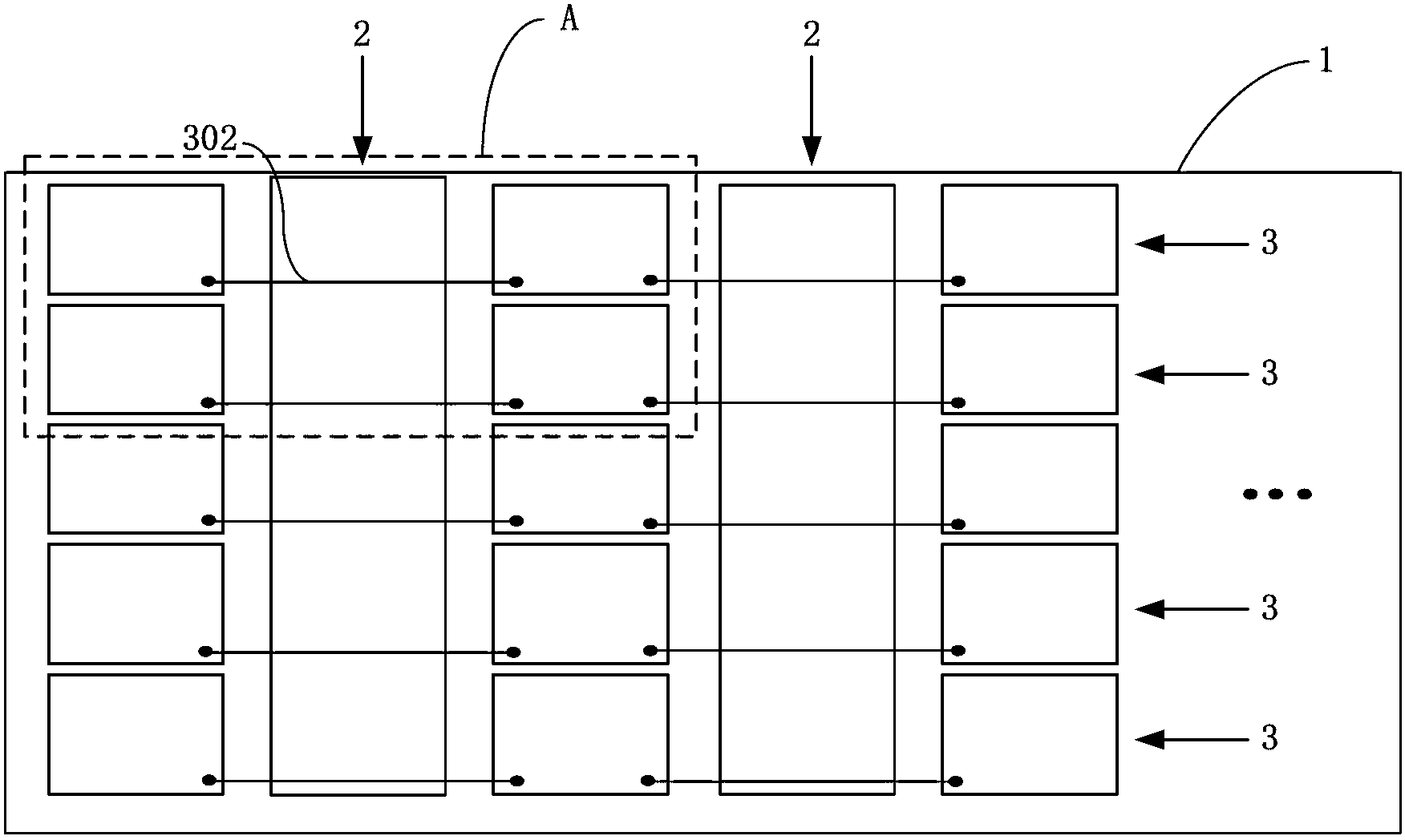
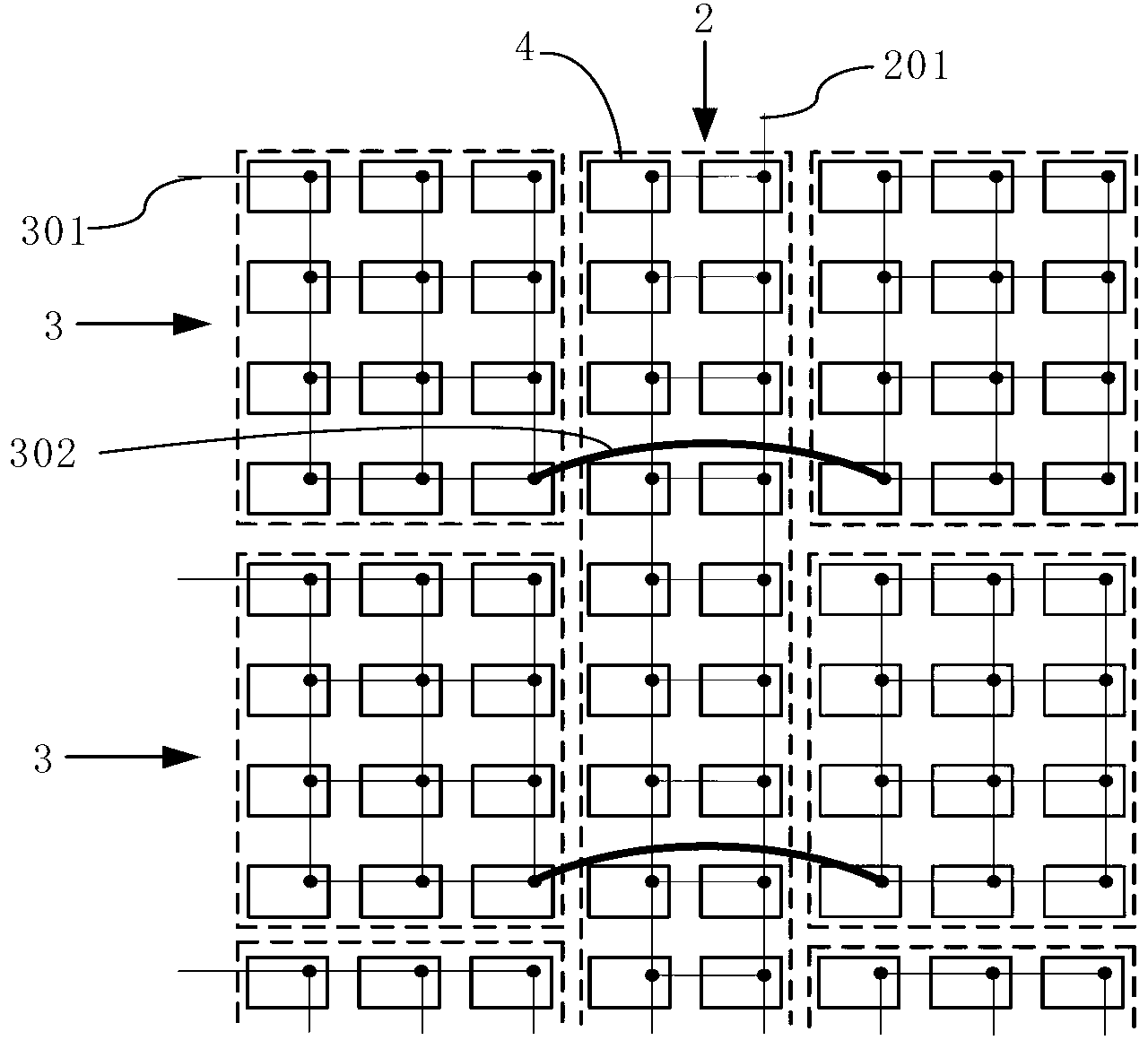
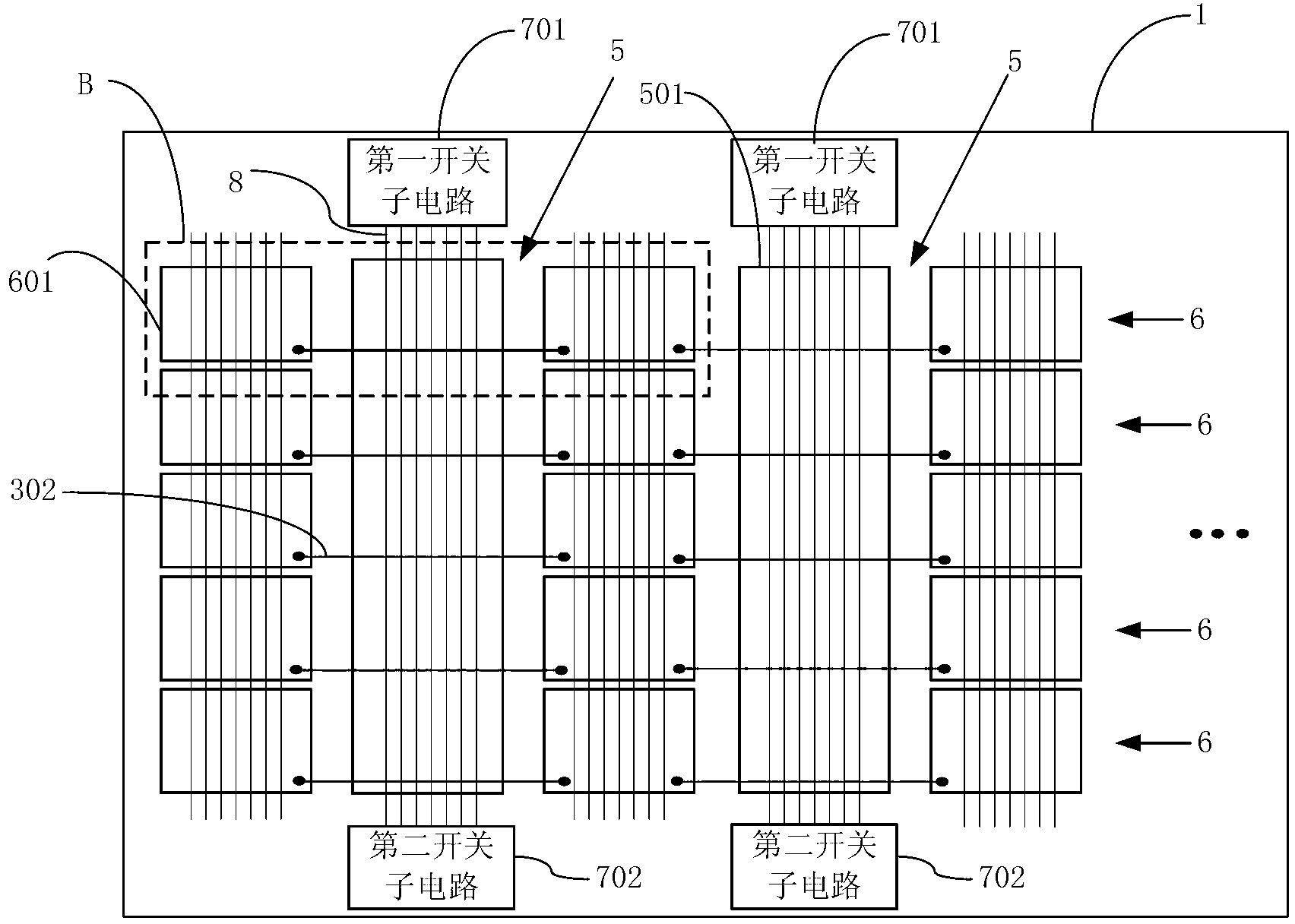
[0043] image 3 It is a schematic structural diagram of the array substrate provided in Embodiment 1 of the present invention, Figure 4 for image 3 The partial enlarged view of the B structure shown, as image 3 and Figure 4 As shown, the array substrate includes: a base substrate 1, on which gate lines, data lines 8, first common electrodes 5 and second common electrodes 6 are formed, the gate lines and data lines 8 define pixel units, Each pixel unit includes a corresponding common electrode base 4, and all the common electrode bases 4 are divided into a plurality of horizontal electrode groups 601 arranged in the row direction and a plurality of vertical electrode groups 501 arranged in the column direction, and the second common electrode 6 includes: a horizontal electrode group 601 on the same row and a metal jumper 302 connecting two adjacent horizontal electrode groups 601 on the same row, and the first common electrode 6 includes: a vertical electrode group 501, ...

Embodiment 2

[0058] Embodiment 2 of the present invention provides a touch screen. The touch screen includes: an array substrate and a color filter substrate. The array substrate and the color filter substrate are arranged oppositely. The described content will not be repeated here.

[0059] The touch screen provided by Embodiment 2 of the present invention includes an array substrate and a color filter substrate. The array substrate includes a base substrate on which gate lines, data lines, first common electrodes, and second common electrodes are formed. A switch circuit is provided between the common electrode and the data line to connect the first common electrode and the data line in parallel during the touch scanning phase. The data lines are connected in parallel, so that the equivalent resistance of the first common electrode is reduced, and the signal-to-noise ratio of the first common electrode is indirectly improved, so that the monitoring of the voltage signal coupled from the ...

Embodiment 3

[0061] Embodiment 3 of the present invention provides a driving method of a touch screen, the driving method includes: in the touch scanning phase, the switch circuit is turned on, so that the first common electrode and the data line are connected in parallel, and the first common electrode or the second common electrode is loaded Touch scanning signal; in the display scanning stage, the switch circuit is disconnected, so that the first common electrode and the data line are disconnected, the display scanning signal scans the gate lines row by row, and the corresponding data line is loaded with the display scanning signal.

[0062] In the driving method of the touch screen provided by Embodiment 3 of the present invention, a switch circuit is provided between the first common electrode and the data line to conduct in the touch scanning phase so that the first common electrode and the data line are connected in parallel. In the control scanning stage, the first common electrode ...


PUM


Abstract

The invention provides an array substrate, a touch screen, a drive method and a display device. The array substrate comprises a substrate, wherein a grid line, a data line, a first public electrode and a second public electrode are formed on the substrate; the second public electrode comprises transverse electrode groups positioned in the same row and metal jumper wires connected with the adjacent two transverse electrode groups in the same row; the first public electrode comprises longitudinal electrode groups; and a switch circuit conducted in a touch control scanning stage to enable the first public electrode and the data line to be connected in parallel is arranged between the first public electrode and the data line. During the touch control scanning stage, the switch circuit is conducted to enable the first public electrode and the data line to be connected in parallel, so that the equivalent resistance of the first public electrode is reduced, the signal-to-noise ratio of the first public electrode is indirectly increased, a voltage signal generated by coupling of a touch control sensing electrode can be more accurately monitored, and a touch point can be accurately positioned.

Description

technical field [0001] The present invention relates to the field of display technology, in particular to an array substrate, a touch screen, a driving method and a display device. Background technique [0002] With the rapid development of display technology, touch screen panels (Touch Screen Panels) have gradually spread throughout people's lives. Currently, touch screens can be classified into resistive, capacitive, infrared and surface acoustic wave types according to their working principles. Among them, the capacitive in-cell touch screen is sought after by the industry as a new favorite due to its unique touch principle, high sensitivity, long life, high light transmittance and other advantages. [0003] The traditional capacitive embedded touch screen is realized by directly adding touch scanning lines and touch sensing lines on the TFT (Thin Film Transistor, Thin Film Field Effect Transistor) array substrate. Intersecting strip-shaped ITO electrodes, these two lay...

Claims


Application Information

Patent Timeline
Patent Type & Authority Applications(China)
IPC IPC(8): G06F3/044
CPCG06F3/0412G06F3/0445G06F3/0446
Inventor 赵家阳张元波秦纬邹祥祥
Owner BOE TECH GRP CO LTD
Why Eureka
Try Eureka