Lift for outdoor substation bus operation

A technology for elevators and substations, which is applied to hoisting devices, overhead lines/cable equipment, etc., and can solve problems such as high cost, high force, and low speed

Inactive Publication Date: 2013-09-18
STATE GRID CORP OF CHINA +1
View PDF1 Cites 8 Cited by
  • Summary
  • Abstract
  • Description
  • Claims
  • Application Information

AI Technical Summary

Problems solved by technology

At present, the main solution is: spend a lot of money to hire a large mechanical crane, which can only be solved with the help of the strength of the boom, which will cost a lot of money and power outage time
When it is impossible to use large-scale mechanical cranes and other equipment in a special work site, maintenance workers have to climb on the high-voltage bus to carry out "swinging" dangerous operations, which brings great safety hazards to the staff
In the existing patents, there are worm gears and worm driving methods for the transmission mechanism of the aerial work elevator for the elevator. For example, the hand-operated aerial work elevator with the patent number "200720107495.3" adopts this transmission method, but the distance between it and the handle The speed is low and the force is high, so it cannot move quickly

Method used


Image

  • Lift for outdoor substation bus operation
  • Lift for outdoor substation bus operation
  • Lift for outdoor substation bus operation

Examples


specific Embodiment approach

[0013] Specific implementation manners: the present invention is not limited by the following examples, and specific implementation manners can be determined according to the technical solutions of the present invention and actual conditions.

Embodiment

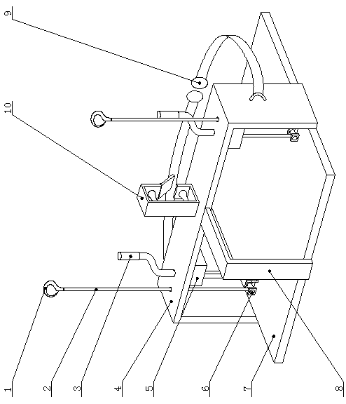
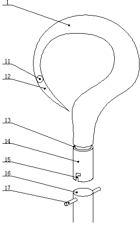
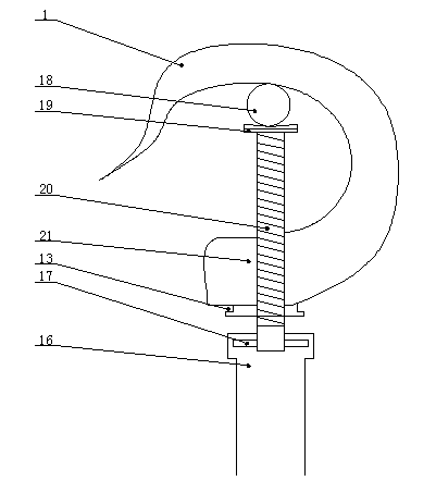
[0014] Example: such as figure 1 As shown, the substation outdoor busbar operation elevator is composed of a base 7, a steel frame 4 fixed on the base 7, a lifter 5 and a glider 10 installed on the steel frame 4. The rear part in the base 7 straddles the channel-shaped steel frame 4, and a lifter 5 is installed on both sides of the lower end surface of the steel frame 4 beams, and the crank handle 3 of the lifter 5 passes through the beam and is exposed on the upper end surface of the beam. Runner 6 is set on base plate 7 both sides, and the steel cable 2 of lifter 5 walks around runner 6 downwards earlier, turns to 180 ° again and is passed by steel frame 4 crossbeams, and the uppermost end links to each other with hook 1. The glider 10 is set in the middle of the beam. The operator sits on the base 7. For ensuring the safety of the operator, a baffle plate 8 is installed at the front end of the base 7 to the middle part of the steel frame 4 beams, and a safety buckle 9 is i...


PUM


Abstract

The invention relates to a lift for outdoor substation bus operation. The life for the outdoor substation bus operation comprises a base, a steel frame, a lifter and a glider, wherein the steel frame is fixed on the base, and the lifter and the glider are arranged on the steel frame. The lift for the outdoor substation bus operation is characterized in that the middle and rear potion of the base stretches across the groove steel frame; the lifter is disposed on both sides of a lower end surface of a crossbeam of the steel frame; a crank of the lifter passes through the crossbeam and exposes on an upper end surface of crossbeam; wheels are arranged on both ends of the base; steel cables of the lifter first bypass the wheels downwards and then pass through the crossbeam of the steel frame, and the top end of the steel cables are connected with a hook; the glider is arranged in the middle of the crossbeam; a drive mechanism provided with a pair of a worm wheel and a worm shaft which are engaged with each other is installed inside the lifter; a rotation shaft of the worm shaft is in linkage with a driven wheel which is engaged with a driving wheel; a rotation shaft of the driving wheel stretches out of a shell of the lifter to be connected with the crank; and a rotation shaft of the worm wheel is in linkage with a rope wheel with cables wound around. The lift for the outdoor substation bus operation is capable of allowing staff to sit in a hanging basket and to turn a handle of the lift to achieve vertical lift. Furthermore, with the drive mechanism for increasing the speed of the lifting, the speed of the lift is fast so that work efficiency is improved.

Description

technical field [0001] The invention relates to an electric power overhead operation device, in particular to an outdoor busbar operation elevator of a substation for high-voltage line suspension operation applied to T-shaped wires in overhead conductors. Background technique [0002] The multi-strand soft busbars in the power grid and the T-type down-conductors in the overhead conductors need to be inspected or repaired. The main solution at present is: spend a large sum of money to hire a large-scale mechanical crane, which can be solved with the help of the strength of the boom arm, which will cost a lot of money and power outage time. When it is impossible to deploy large-scale mechanical cranes and other equipment in a special work site, maintenance workers have to climb on the high-voltage bus to carry out "swinging" dangerous operations, which brings great safety hazards to the staff. In the existing patents, there are worm gears and worm driving methods for the tra...

Claims


Application Information

Patent Timeline
Patent Type & Authority Applications(China)
IPC IPC(8): H02G1/02B66F11/04
Inventor 谢林海牛贵强胥晓龙艾尼瓦尔·吐尔逊
Owner STATE GRID CORP OF CHINA
Why Eureka
Try Eureka