Supercharge Your Innovation With Domain-Expert AI Agents!

Machining method of floating cylinder

A floating sleeve and processing method technology, applied in the field of mechanical processing and manufacturing, can solve problems such as difficult clamping, and achieve the effect of ensuring processing quality and improving process solutions.

Active Publication Date: 2013-09-25
DONGFANG TURBINE CO LTD
View PDF7 Cites 16 Cited by
  • Summary
  • Abstract
  • Description
  • Claims
  • Application Information

AI Technical Summary

Problems solved by technology

Finally, due to the length and structure of the workpiece, faceting in milling and clamping in turning are difficult

Method used


Image

  • Machining method of floating cylinder
  • Machining method of floating cylinder
  • Machining method of floating cylinder

Examples


Embodiment Construction

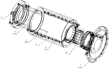
[0034] Such as Figure 1~3 As shown, the floating sleeve to be processed is in the shape of a sleeve, and the two ends are designed with journals and end flanges. The floating sleeve has an upper and lower half structure. The flange 5 is provided with a connection hole 4, and the upper half and the lower half of the floating sleeve are fastened by bolts.

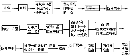
[0035] The present invention is a processing method for the above-mentioned floating sleeve, comprising the following steps:

[0036] (1) The upper half and the lower half of the workpiece to be processed are sequentially clamped on the machine tool for rough machining, specifically: rough milling the upper half of the workpiece and the mid-section of the lower half of the workpiece, and pre-drilling the mid-section method of the upper half of the workpiece The connection hole 4 on the blue 5, the drain hole on the lower half of the pre-milled workpiece;

[0037] Wherein: the upper half of the workpiece or the lower half o...


PUM


Abstract

The invention provides a machining method of a floating cylinder. The method includes the steps of roughing an upper half and a lower half of a work piece; integrating the upper half of the work piece and the lower half of the work piece, and subjecting external and inner peripheries of the work piece to allowance rough turning; demounting and sequentially finish-milling a split between the upper half and the lower half; bolting and subjecting external and internal peripheries of a work piece journal to allowance semi-finish-turning; reaming connecting holes, an oil inlet and an oil outlet; milling a fine thread on the oil inlet, an oil way of the upper half of the work piece and connecting holes in an end flange; demounting and sequentially finish-milling the upper half and the lower half; bolting and finish-turning the outer periphery of the work piece; demounting, cleaning the surface and checking surface quality of the external and internal peripheries of the work piece; bolting and oiling before storage. The method has the advantages that application requirements are met, machining quality is well guaranteed, the problems possibly existing in production of new products are solved, the size tolerance and external beating can be ensured to meet the technical requirements, and a reasonable complete process scheme for machining of subsequent products is provided.

Description

technical field [0001] The invention relates to the field of mechanical processing and manufacturing, in particular to a processing method for a floating sleeve used in a turbine test bench. Background technique [0002] Such as figure 1 Shown is a floating sleeve for a turbine test rig. During assembly, a rotating shaft is arranged inside the floating sleeve, and the floating sleeve is arranged inside the bearing housing. The left journal 2 and the right journal 6 are respectively designed on the left and right sides of the floating sleeve, and the inner holes and the outer circles of the left journal 2 and the right journal 6 are equipped with dynamic bearings and static bearings. The static bearing of its left journal 2 or the right journal 6 outsides is supported on the bearing housing, and the dynamic bearing sleeve of the left journal 2 and the right journal 6 inboards is on the rotating shaft. When the floating sleeve is in use, the outer bearing housing is fixed, ...

Claims


Application Information

Patent Timeline
IPC IPC(8): B23P15/00
Inventor 曾强冷进明唐仕东朱永祥谢敏刘家顺孟秋建谭云李松林崔志国刘艳平周万煜
Owner DONGFANG TURBINE CO LTD
Features
  • R&D
  • Intellectual Property
  • Life Sciences
  • Materials
  • Tech Scout
  • Unparalleled Data Quality
  • Higher Quality Content
  • 60% Fewer Hallucinations
Learn More