
Hollow injection molding method

An injection molding, hollow technology, applied in the direction of hollow objects, other household appliances, household appliances, etc., can solve the problems of increasing investment costs, consuming manpower and material resources and factory space, saving manpower and material resources, improving the stability of assembly quality and coordination tightness effect

Inactive Publication Date: 2013-09-25
BORCH MACHINERY
View PDF0 Cites 5 Cited by
  • Summary
  • Abstract
  • Description
  • Claims
  • Application Information

AI Technical Summary

Problems solved by technology

[0002] Traditionally, blow molding is often used when hollow-molded plastic parts are required, or multiple or single injection molding machines and multiple sets of molds are produced in a single way, and then manually or mechanized assembly is performed for secondary injection molding, but blow molding has certain limitations. Sex, cannot achieve hollow sealing performance at one time
Although with the development of technology, multi-material and multi-color injection molding machines have appeared, which can form multiple materials or multi-color injection molding at one time, it is still impossible to perform those hollow sealed injection molded parts that require secondary processing, which requires more equipment or manpower for secondary processing. Secondary processing consumes manpower, material resources and workshop space, increasing investment costs

Method used


Image

  • Hollow injection molding method
  • Hollow injection molding method
  • Hollow injection molding method

Examples


Embodiment Construction

[0012] The present invention will be further described in detail below in conjunction with the accompanying drawings and embodiments.

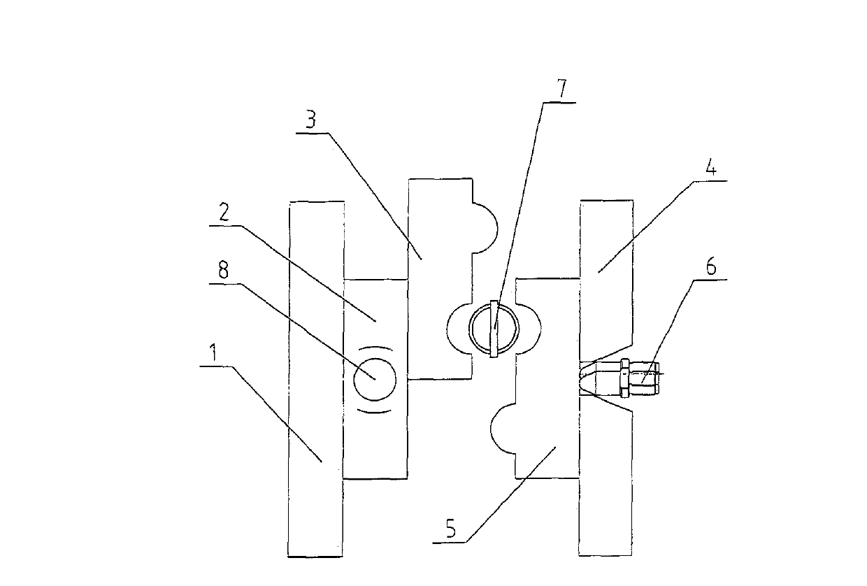
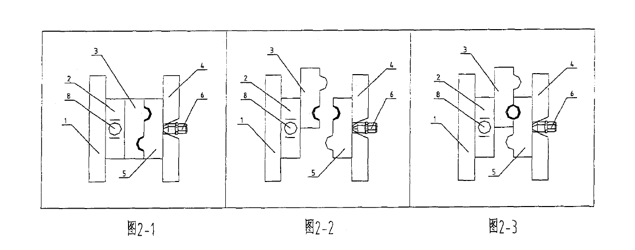
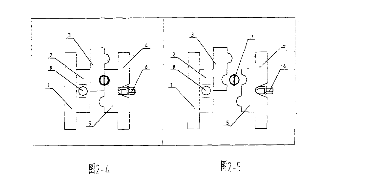
[0013] Such as figure 1 As shown, a method of hollow injection molding, comprising a moving plate (1), a moving mold (2), a sub-mold driving device (8), a sub-mold (3), a fixed plate (4), a fixed mold (5), injection mechanism (6) and produced products (7); it is characterized in that: the movable mold (2) is installed on the movable plate (1), the fixed mold (5) is installed on the fixed plate (4), and the movable mold (2) , sub-mold (3), fixed mold (5) after mold closing is completed, the injection mechanism (6) of the injection molding machine performs the first injection action, and the two stations in the mold are respectively injected into two halves of the product, and then the mold is opened, and the movable mold (2 ) through the sub-mold driving device (8) to drive the sub-mold (3) to match the next station, and then the injection mol...


PUM


Abstract

The invention relates to a hollow injection molding method including a movable plate, a movable mold, a sub mold driving device, a sub mold, a fixed plate, a fixed mold and an injection molding mechanism. The method is characterized in that: after the movable mold, the sub mold, the fixed mold complete mold clamping to obtain a mold, an injection molding machine performs an injection action, after finishing the injection, the mold is opened to a required distance, the movable mold drives the sub mold to match a next station by the sub mold driving device, then the mold clamping is carried out again, original separated different part products are spliced together, then a secondary injection is carried out, the separated different products perform injection molding together by plastics, and hollow injection molding products are obtained. Thought the hollow injection molding method, some procedures that need a second processing especially withrealing hollow products which need welding, are designed to be carried out in the mold, withrealing hollow plastic parts are final products when leaving a mold cavity, the quality stability and the combining tightness of a product assembly are improved, and manpower, material resources and workshop space are saved.

Description

Technical field [0001] The invention relates to a hollow injection molding method, in particular to a hollow injection molding method with a seal for improving the production efficiency and quality of injection molding of an injection molding machine. Background technique [0002] Traditionally, blow molding is often used when hollow-molded plastic parts are required, or multiple or single injection molding machines and multiple sets of molds are produced in a single way, and then manually or mechanized assembly is performed for secondary injection molding, but blow molding has certain limitations. Sex, can not achieve hollow sealing performance at one time. Although with the development of technology, multi-material and multi-color injection molding machines have appeared, which can form multiple materials or multi-color injection molding at one time, it is still impossible to perform those hollow sealed injection molded parts that require secondary processing, which requir...

Claims


Application Information

Patent Timeline
IPC IPC(8): B29C45/10B29L22/00
Inventor 黄土荣
Owner BORCH MACHINERY
Learn More