
Diaphragm automatic turning machine

A technology of automatic flipping and diaphragm

Active Publication Date: 2015-09-30
SICHUAN CHANGHONG ELECTRIC CO LTD
View PDF5 Cites 1 Cited by
  • Summary
  • Abstract
  • Description
  • Claims
  • Application Information

AI Technical Summary

Problems solved by technology

[0003] The present invention overcomes the deficiencies of the prior art, and provides an automatic diaphragm turning machine, in order to solve the problems of inconvenient manual operation, low work efficiency and high cost of diaphragm reversal in the prior art.

Method used


Image

  • Diaphragm automatic turning machine
  • Diaphragm automatic turning machine
  • Diaphragm automatic turning machine

Examples


Embodiment Construction

[0019] The present invention will be further elaborated below in conjunction with the accompanying drawings.

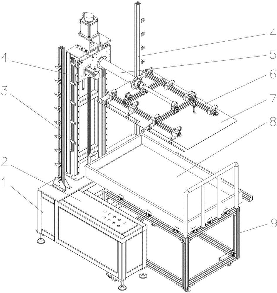
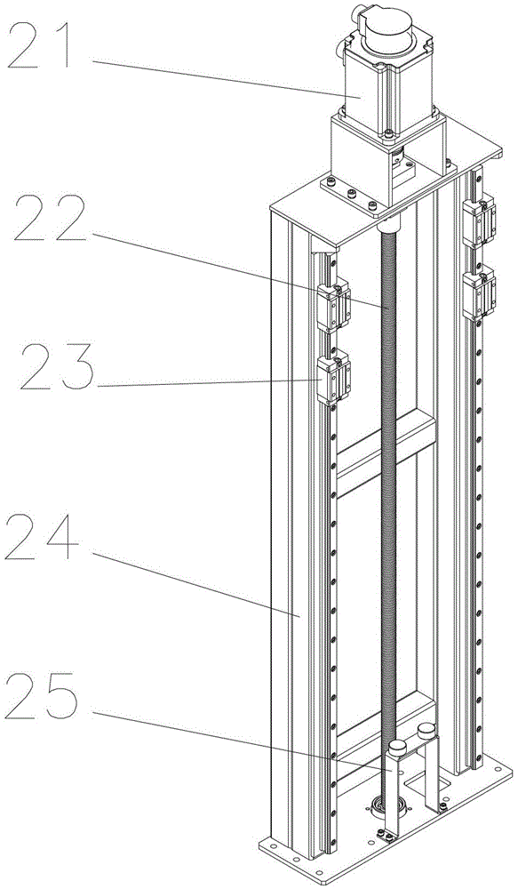
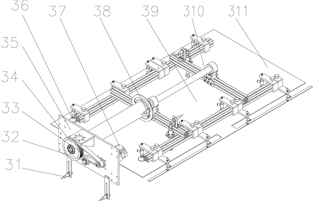
[0020] Such as figure 1 as shown, figure 1 A schematic diagram of the overall structure of an automatic diaphragm turning machine according to an embodiment of the present invention is shown. The diaphragm automatic turning machine of this embodiment includes a frame 1, an electric control box 2 is arranged on the left side of the frame 1, and an electric control system is equipped in the electric control box 2. A vertical motion mechanism 4 is arranged on the middle part of the frame 1, and the vertical motion mechanism 4 is fixed on the frame 1 by nuts. A rotary motion mechanism 5 is horizontally arranged on the vertical motion mechanism 4, and a vacuum adsorption mechanism 6 is arranged at the lower end of the rotary motion mechanism 5. A vacuum suction cup is arranged on the vacuum suction mechanism, and the vacuum suction cup can be used to suck the diaphragm 7...


PUM


Abstract

The invention discloses an automatic membrane turning machine which comprises a machine frame. An electric control box is arranged on the machine frame. An electric control system is arranged in the electric control box. A vertical moving mechanism is arranged on the machine frame. A rotation moving mechanism is arranged on the vertical moving mechanism transversely. A vacuum absorbing mechanism is arranged on the rotation moving mechanism. The vertical moving mechanism is connected with the electric control system. The rotation moving mechanism is connected with the electric control system. The electric control system is connected with the vacuum absorbing mechanism. A membrane storing box is arranged below the vacuum absorbing mechanism. The automatic membrane turning machine achieves automatic operation of membrane turning, achieves a safety monitoring function and is safe to operate by using a vacuum absorbing system.

Description

technical field [0001] The invention relates to an automatic turning device, in particular to a diaphragm automatic turning machine. Background technique [0002] The turning machine can adapt to the turning requirements of goods of different specifications, provide safe, stable and effective process transportation, and realize the operation goal of converting goods from horizontal to vertical or from vertical to horizontal. In the field of electrical appliance or mold manufacturing, assembly line operations on the production line often require turning over a single diaphragm or plate mold to achieve the next step of production. The flipping work of the diaphragm in the prior art is done manually, which is not only harmful to the health of the human body, but also has low work efficiency and high labor costs. At the same time, because the size of the diaphragm is too large, it is not conducive to manual turning operation. Contents of the invention [0003] The invention ...

Claims


Application Information

Patent Timeline
Patent Type & Authority Patents(China)
IPC IPC(8): B65H15/00
Inventor 潘晓勇巫江符欣程占江王光伦
Owner SICHUAN CHANGHONG ELECTRIC CO LTD
Learn More