Spool with wire clamp
A technology for winding spools and clamping wires, applied in the field of spools, can solve the problems of reducing production efficiency, easy to fall off, simple structure, etc., and achieve the effect of improving work production efficiency
Inactive Publication Date: 2013-09-25
WUXI TONGXIN PLASTIC PROD
View PDF9 Cites 1 Cited by
- Summary
- Abstract
- Description
- Claims
- Application Information
AI Technical Summary
Problems solved by technology
However, most of the winding shafts in the past have simple structures, and they are easy to fall off after winding, which reduces the production efficiency.
Method used
View moreImage
Smart ImageViewing Examples

Examples
Embodiment 1
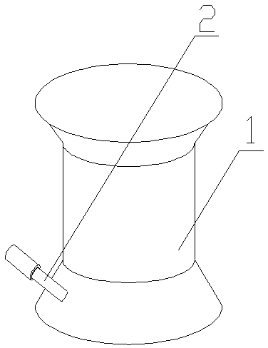
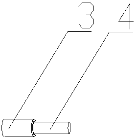
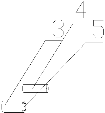
[0012] Such as Figure 1-4 As shown, the winding shaft with the wire clamping device, the winding shaft 1 is an I-shaped spool, the winding shaft 1 is provided with the wire clamping device 2, the wire clamping device 2 is composed of the outer cylinder 3 and the inner column 4, and one end of the inner column 4 It is fixedly connected to the inside of one end of the winding shaft 1, the outer cylinder 3 is cylindrical with one end open, the inner column 4 is cylindrical, the diameter of the cavity 5 in the outer cylinder 3 is greater than the diameter of the inner column 4, the outer cylinder 3 and the inner column 4 is socket.
Login to View More PUM
 Abstract
The invention discloses a spool with a wire clamp. The spool is characterized in that the spool is an I-shaped spool, the wire clamp is disposed on the spool and comprises an outer cylinder and an inner post, one end of the inner post is fixedly connected to the inner side of one end of the spool, the outer cylinder is in a cylinder shape having an opening at one end, the inner post is also cylindrical, the diameter of an inner cavity of the outer cylinder is larger than that of the inner post, and the outer cylinder is sleeved on the inner post. The spool has the advantages that after a wire is tightly wound, the wire end is wound on the inner post before the inner post is sleeved with the outer cylinder; accordingly, the wire end is tightly clamped and rarely drops, and work efficiency and production efficiency are improved.
Description
technical field [0001] The invention relates to a bobbin with a thread clamping device. Background technique [0002] In the field of textile production, a large number of plastic winding spools are used, mostly I-shaped spools. However, most of the previous winding shafts have simple structures and are easy to fall off after winding, which reduces the production efficiency. Contents of the invention [0003] The object of the present invention is to provide a winding shaft with a wire clamping device which is not easy to fall off for the above-mentioned defects in the prior art. [0004] In order to achieve the above object, the technical solution provided by the present invention is: a winding shaft with a clamping device. 2 is composed of an outer cylinder 3 and an inner column 4, one end of the inner column 4 is fixedly connected to the inner side of one end of the winding shaft 1, the outer cylinder 3 is cylindrical with one end open, and the inner column 4 is cylin...
Claims
Login to View More Application Information
Patent Timeline
 IPC IPC(8): B65H75/28
Inventor 钱嘉良
Owner WUXI TONGXIN PLASTIC PROD