
Smart electric switch sliding sleeve

An electric switch and sliding sleeve technology, which is applied in the fields of production fluids, wellbore/well components, earth-moving drilling, etc., can solve the problems of increased cost and prolonged operation time, and achieves a construction cost saving, simple construction and strong integrity. Effect

Active Publication Date: 2015-10-07
CHINA PETROLEUM & CHEM CORP +1
View PDF7 Cites 0 Cited by
  • Summary
  • Abstract
  • Description
  • Claims
  • Application Information

AI Technical Summary

Problems solved by technology

Both methods involve multi-step downhole operations including perforating, switching sleeves, bridge plugging, and subsequent coiled tubing milling, resulting in longer and more expensive operations

Method used


Image

  • Smart electric switch sliding sleeve
  • Smart electric switch sliding sleeve
  • Smart electric switch sliding sleeve

Examples


Embodiment Construction

[0022] The present invention will be further described below in conjunction with accompanying drawing.

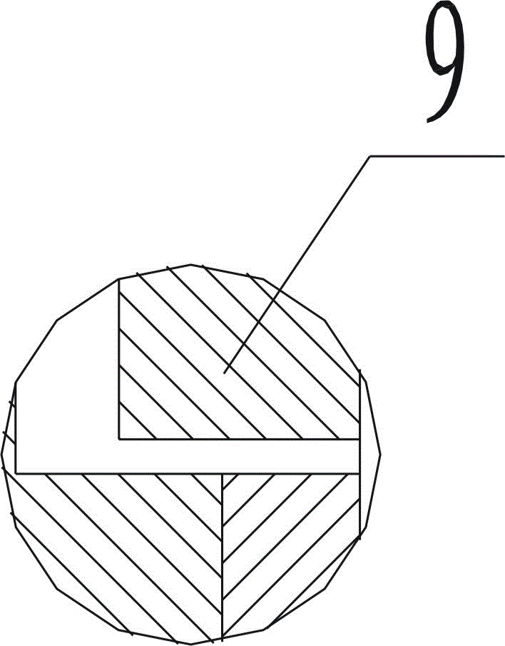
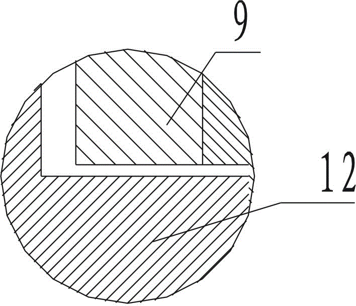
[0023] Such as figure 1 , 2 , 3, the intelligent electric switch sliding sleeve includes an upper variable button joint 1, a hydraulic piston 2, a first manifold joint 4, a second manifold joint 9, a power piston 10, a sliding sleeve outer cylinder 12, and a sliding sleeve core 11 , the lower variable button joint 13 and the circuit control module, the upper variable button joint 1 is set on the upper end of the first manifold joint 4, the hydraulic piston 2 is set on the upper end of the first manifold joint 4, and its lower end is connected with the upper variable button joint 1 The inner wall and the outer wall of the first manifold joint 4 form a hydraulic chamber 3, and a discharge cavity 5 is provided between the inner wall of the upper change button joint 1 and the outer wall of the first manifold joint 4, and the lower end of the first manifold joint 4 is connected...


PUM


Abstract

The invention discloses an electric intelligent switching sliding sleeve. The electric intelligent switching sliding sleeve comprises an upper adapter connector, a hydraulic piston, a first pipe joint connector, a second pipe joint connector, a power piston, a sliding sleeve outer casing, a sliding sleeve core, a lower adapter connector and a circuit control module. The hydraulic piston is mounted on the first pipe joint connector in a sleeved mode, the lower end of the hydraulic piston, the inner wall of the upper adapter connecter and the outer wall of the first pipe joint connector form a hydraulic pressure cavity, a drainage cavity is further arranged between the upper adapter connector the first pipe joint connector, the lower end of the power piston is connected with the sliding sleeve core, and the periphery of the power piston is provided with flanges for being configured with the second pipe joint connector in a seal mode. The electric intelligent switching sliding sleeve can achieve the full drift diameter of the inner diameter of a string and the usage number of the electric switching sliding sleeve is unlimited, accordingly the staged fracturing of horizontal wells and vertical wells is not limited by the number of stages, the construction process is simple and reliable, the reciprocating dragging of the string can be avoided and the construction cost can be saved.

Description

technical field [0001] The invention relates to a downhole tool used for fracturing and acidizing measures in oil and gas field development. Background technique [0002] In recent years, with the increasing difficulty of oil and gas field development and the advancement of drilling and production technology, the proportion of directional wells and horizontal wells is also increasing. Following this, single-well multi-layer / stage fracturing and acidizing technology has become an oil and gas field stabilization technology. It is an important measure to increase production, which puts forward higher requirements for the key tools supporting fracturing and acidizing downhole. [0003] At present, oil and gas horizontal wells and vertical wells are divided into staged acidizing and fracturing methods, including flow-limiting fracturing and staged fracturing. The mainstream is staged fracturing, including chemical staged fracturing, packer staged fracturing, hydraulic jet fractur...

Claims


Application Information

Patent Timeline
Patent Type & Authority Patents(China)
IPC IPC(8): E21B43/27E21B34/16E21B34/06
Inventor 赵忠建汪团员谢小辉樊丽丽宋俊
Owner CHINA PETROLEUM & CHEM CORP
Learn More