Eureka AIR delivers breakthrough ideas for toughest innovation challenges, trusted by R&D personnel around the world.

Pump aggregate

An assembly and shell technology, applied in the direction of pumps, multi-cylinder pumps, pump components, etc., can solve the problems of high directional control valve, large pump assembly, large size, etc., to achieve increased weight saving, high uniformity, weight saving effect

Inactive Publication Date: 2013-09-25
哈维液压欧洲公司
View PDF8 Cites 2 Cited by
  • Summary
  • Abstract
  • Description
  • Claims
  • Application Information

AI Technical Summary

Problems solved by technology

From this arrangement, the specific performance specifications for the pump assembly result in a relatively large weight, which, important and especially for portable tool assemblies fitted with the pump assembly, presents a considerable disadvantage
Furthermore, a disadvantage is the relatively high and bulky size of the valve combination and the directional control valve located on the outside of the housing, the valve combination is mounted to the outer wall of the housing at the two pressure outlets, due to the vibrations caused by operation, this size in The location of these two pressure outlets causes considerable local stress on the housing

Method used


Image

  • Pump aggregate
  • Pump aggregate
  • Pump aggregate

Examples


Embodiment Construction

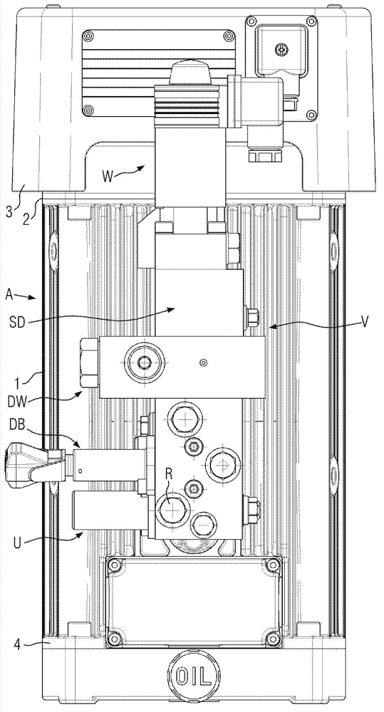
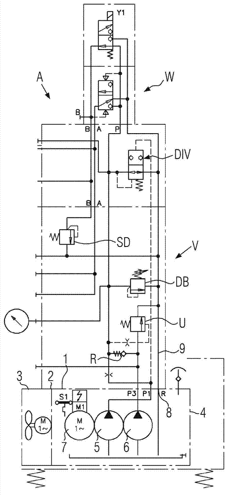
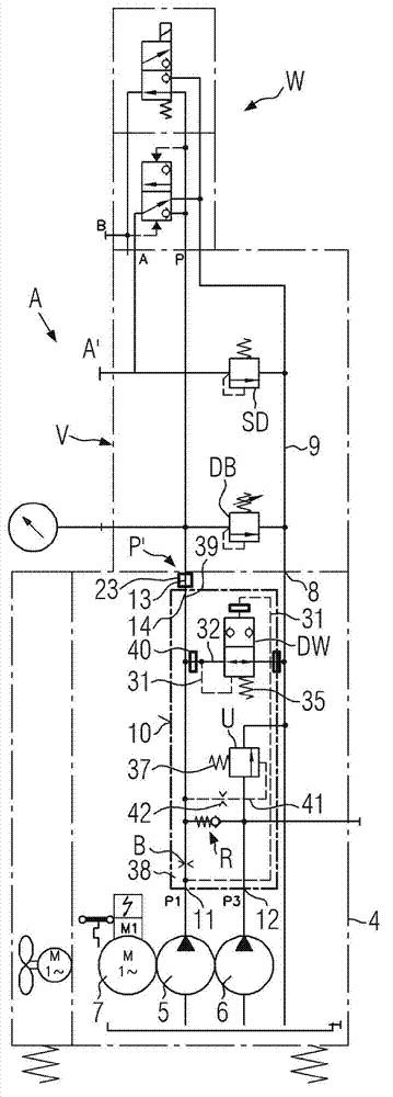
[0034] refer to explaining figure 1 and 2 prior art reference numerals used for equipment parts, in each embodiment of the pump assembly A showing the present invention Figures 3 to 15 Equipment parts with the same function and reference numerals also appear in .

[0035] Compared figure 1 and 3It has been shown that for a given performance specification the housing 1, 2, 3, 4 of the pump assembly A according to the invention has the same figure 1 The same external dimensions as the known pump assembly A. However, in figure 1 In the known pump assembly A in , the external valve combination V consists of a low pressure changeover valve U, a check valve R, a system pressure limiting valve DB, a pressure bypass switch DW with a dispensed orifice B and optionally an auxiliary pressure limiting valve SD ( image 3 ). Now, the pump unit A according to the invention comprises only the system pressure limiting valve DB, an optionally provided auxiliary pressure limiting valve ...


PUM


Abstract

A pump aggregate (A) comprises a housing (1, 2, 4), a high-pressure pump (5) and a low-pressure pump (6) disposed in the housing, an oil-immersed electric motor (7), a return connection point (8) connected to a return line (9), and a valve arrangement (V) mounted between separated discharge outlet ports of both pumps (5, 6) and a pressure connection point (P). The valve arrangement (V) comprises at least a low-pressure change-over valve (U), a check valve (R) for combining discharge flows of both pumps (5, 6), and a system pressure-limiting valve (DB). At least the low-pressure change-over valve (U) and the check valve (R) are arranged in an interior of the housing (1, 2, 4) and are connected so that the discharge flows of both pumps (5, 6) are combined in the housing interior for a single pressure outlet (13, P') of the housing, and wherein the system pressure-limiting valve (DB) is connected to the pressure outlet and is mounted on an exterior of the housing.

Description

technical field [0001] The invention relates to a pump assembly according to the preamble of claim 1 . Background technique [0002] This pump assembly A ( figure 1 and 2) Manufactured and distributed by the applicant for eg mounting in portable tool assemblies such as torque screwdrivers for generating high tightening torques. This tool assembly is used for assembling wind turbines whereby in one model of an oil-immersed electric motor 7 with single-phase alternating current not activated under pressure, a pressure shunt switch DW is contained in a valve combination V outside the housing. In an assembly model (not shown) that includes a three-phase AC oil-filled motor that does not start under pressure, the pressure shunt switch can be eliminated. The housing, which is often installed in the recumbent operating position, is cooled by an externally ribbed pipe section 1, housing covers 2, 4 mounted on the pipe section and optionally provided cooling on one of the housing c...

Claims


Application Information

Patent Timeline
IPC IPC(8): F04B17/04F04B53/10F04B53/16
CPCF04B17/06F04B1/08F04B17/03
Inventor G·努麦尔
Owner 哈维液压欧洲公司
Why Eureka
Eureka Blog
Learn More