Bimetal liner with flanged flange and manufacturing method of bimetal liner

A bimetallic and bushing technology, applied in the direction of bearing components, shafts and bearings, mechanical equipment, etc., can solve the problems of complex manufacturing process, welding stress, and failure to use normally

Inactive Publication Date: 2013-09-25
ZHEJIANG SF OILLESS BEARING +1
View PDF7 Cites 8 Cited by
  • Summary
  • Abstract
  • Description
  • Claims
  • Application Information

AI Technical Summary

Problems solved by technology

[0002] Many sleeve-shaped sliding bearings are usually made of bimetallic bushings with flanges in order to meet the requirements of axial limit and end face wear resistance, that is, the outer layer of the bushing is made of steel, and the inner lining is made of copper. Alloy layer, the bush is widely used in all kinds of machinery, especially construction machinery, but these bushes are made of cylindrical tubular bushes and ring-shaped gaskets welded on the end face of the bushing and have a flange at one end Bushings, because they are welded at high temperature at the joints, destroy the metallographic structure of the friction surface, and there is welding stress, and turning is required after welding. Therefore, their friction and wear properties and connection strength will be greatly reduced. There are certain hidden dangers in the strength, the manufacturing process is complicated, and the cost is high
Although there are also flanges made by cold stamping directly on one end of the bushing by flanging, but because the copper alloy layer on the flange surface will crack when flanging, the thin-walled (wall thickness 2mm and below) bushing is barely acceptable. The copper layer on the blue surface is slightly cracked
For flanging bushes with a slightly thicker wall thickness (above 2mm), the cracking of the copper alloy layer on the flange surface is more obvious, especially for the flanging bushes with a wall thickness exceeding 3mm, the cracking of the copper alloy on the flange surface is more serious, and it cannot Normal use

Method used


Image

  • Bimetal liner with flanged flange and manufacturing method of bimetal liner
  • Bimetal liner with flanged flange and manufacturing method of bimetal liner
  • Bimetal liner with flanged flange and manufacturing method of bimetal liner

Examples


Embodiment Construction

[0020] The content of the present invention will be further described below in conjunction with the accompanying drawings.

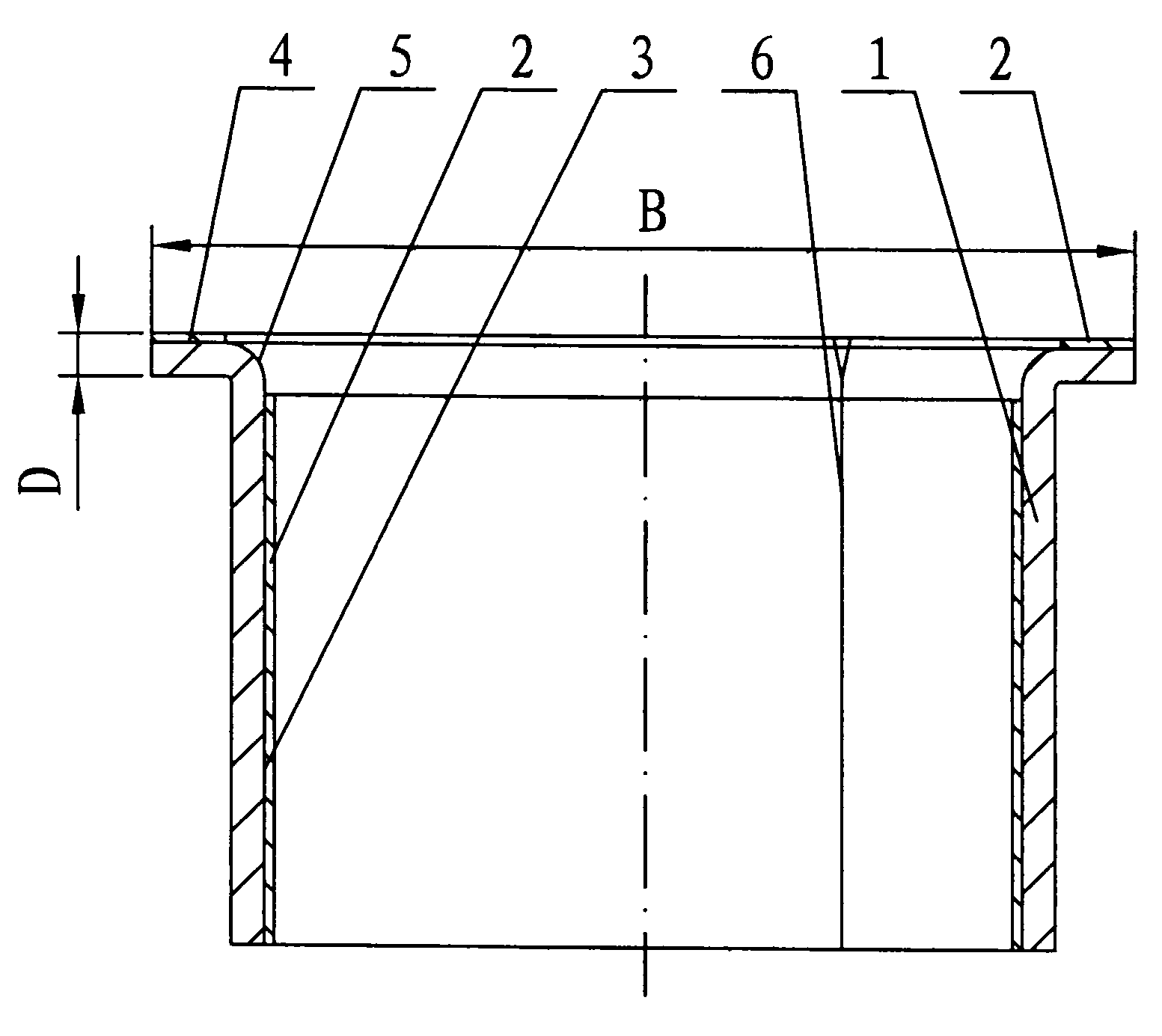
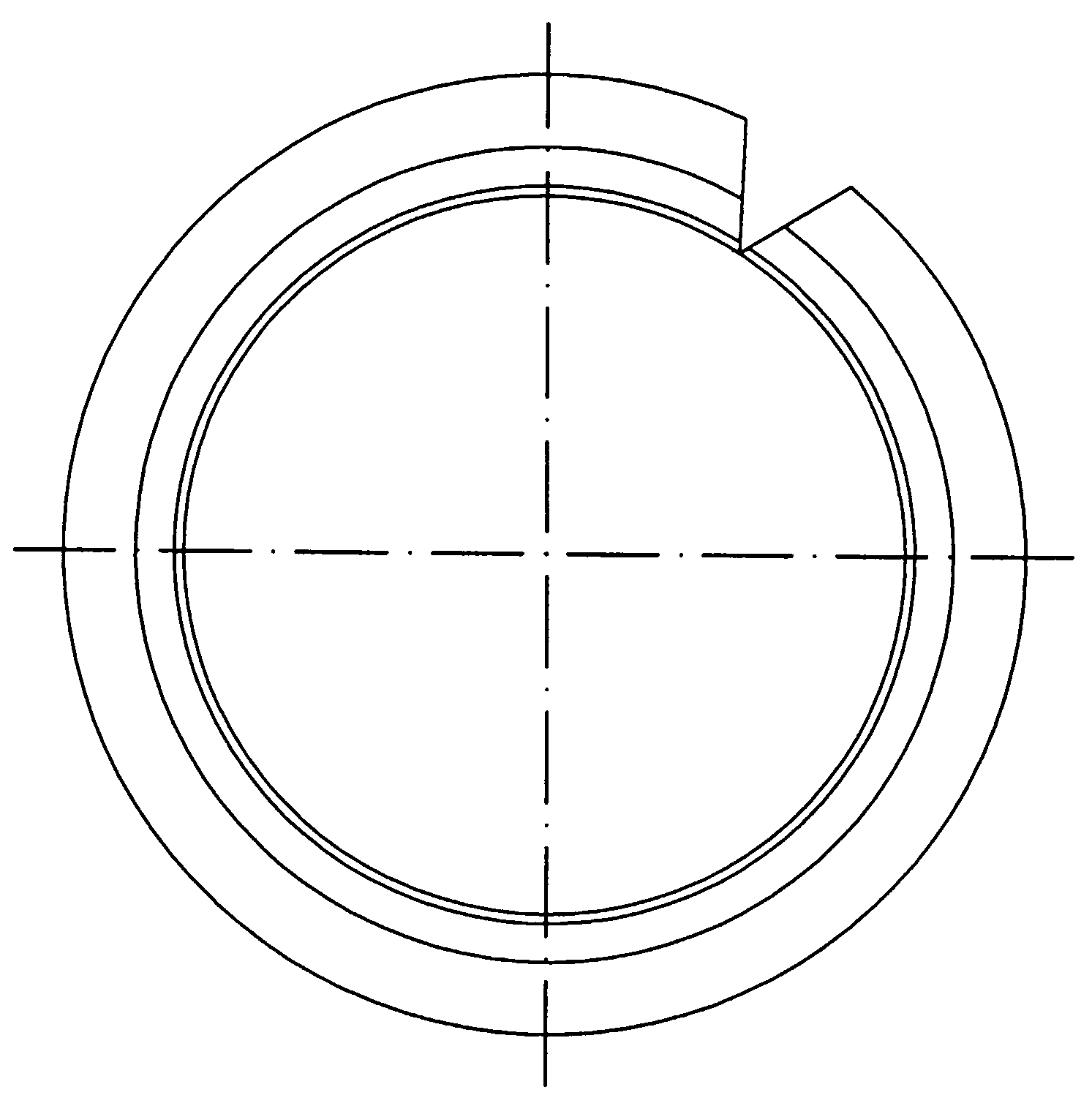
[0021] figure 1 , figure 2 It is a structural diagram of a bimetallic bush with a flanging flange. It can be seen from the figure that it includes a sleeve-shaped bimetallic bushing 3 with an outer layer of steel material 1 and an inner lining of a copper alloy layer 2. One end of the bimetallic bushing 3 is made with an everted flange 4, and the flange 4 is also a bimetallic structure of the steel material 1 and the copper alloy layer 2, and is folded between the bimetallic bushing 3 and the flange 4. There is no copper alloy layer on the outer arc surface 5 of the bend.

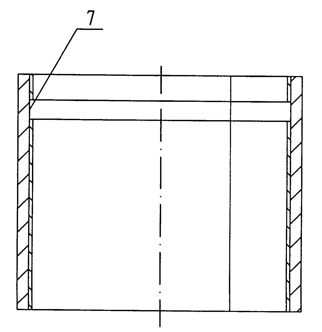
[0022] The manufacture of the bimetallic bushing with flanging flange is to roll the bimetallic sheet material sintered by steel material and copper alloy into a bushing with joint 6. Before flanging, the bimetallic bushing 3. The copper alloy layer 2 on the bending position 7 con...


PUM


Abstract

The invention discloses a bimetal liner with a flanged flange and a manufacturing method of the bimetal liner. The bimetal liner with the flanged flange and the manufacturing method of the flanged flange have the advantages that the structure is simple, the process performance is good, the self-lubricating property is excellent, a copper alloy layer of a flange face cannot crack, and the production efficiency is high. The bimetal liner with the flanged flange comprises a shaft-sleeve-shaped bimetal liner, wherein an outer layer of the bimetal liner is made of steel material, and an inside lining of the bimetal liner is a copper alloy layer; and an outward-flanged flange side is arranged at one end of the bimetal liner and is also in a bimetal structure consisting of the steel material and the copper alloy layer. The bimetal liner is characterized in that the copper alloy layer is not arranged at an outer arc face at a bending part between the bimetal liner and the flange side. As the copper alloy layer is not arranged at the bending part, a situation that the copper alloy layer cracks is avoided in a flanging process. According to a flanging die used in the manufacturing method, the outward-flanged flange side is located in a pit of an upper die, and the outer edge of the flange side is limited by the edge of the pit and cannot extend and deform outwards without limit, so that a phenomenon that the copper alloy layer on the flange side cracks is avoided.

Description

Technical field [0001] The invention relates to a sliding bearing, in particular to a bimetal bush with a flanging flange and a manufacturing method thereof. Background technique [0002] Many sleeve-shaped sliding bearings are usually made of bimetallic bushings with flanges in order to meet the requirements of axial limit and end face wear resistance, that is, the outer layer of the bushing is made of steel, and the inner lining is made of copper. Alloy layer, the bush is widely used in all kinds of machinery, especially construction machinery, but these bushes are made of cylindrical tubular bushes and ring-shaped gaskets welded on the end face of the bushing and have a flange at one end Bushings, because they are welded at high temperature at the joints, destroy the metallographic structure of the friction surface, and there is welding stress, and turning is required after welding. Therefore, their friction and wear properties and connection strength will be greatly redu...

Claims


Application Information

Patent Timeline
Patent Type & Authority Applications(China)
IPC IPC(8): F16C33/06F16C33/14B23P15/00
Inventor 袁翔飞童旭平沈持正蔡根荣沈金祥陈功波陆良平徐跃陈建超陆家豪陈赟杰童永进
Owner ZHEJIANG SF OILLESS BEARING
Why Eureka
Try Eureka