Data collecting device and method

A data acquisition and zero-signal technology, applied in data recording, optical recording/reproduction, instruments, etc., can solve problems such as the inability to smoothly carry out the decoding process, the inability to start the decoding process, and the inability to end the decoding process. Hardware space and production cost, and the effect of reducing the probability of estimating wrong sampling signals

Inactive Publication Date: 2013-09-25
SUNPLUS TECH CO LTD
View PDF4 Cites 3 Cited by
  • Summary
  • Abstract
  • Description
  • Claims
  • Application Information

AI Technical Summary

Problems solved by technology

However, when the four sync bodies whose sync identification code is 0001 or all are damaged or scratched by stains, although the row data in the group cut area is not damaged or scratched, this method will still fall into recursion Difficulties in searching for synchronous ontologies indefinitely, so that the decoding process cannot be started
In addition, when the synchronization body whose synchronization identification code is 1111 is damaged or scratched, this method will not end the decoding process
That is to say, when the synchronization bodies whose synchronization identification codes are 0000 and 0001 are damaged or scratched by stains, this method will not be able to carry out the decoding process smoothly

Method used


Image

  • Data collecting device and method
  • Data collecting device and method
  • Data collecting device and method

Examples


Embodiment Construction

[0073] Figure 4 It is a schematic diagram of a data acquisition device according to an embodiment of the present invention. refer to Figure 4 , the data acquisition device 400 includes a signal processing unit 410 , a frequency locking circuit 420 and a matching circuit 430 . Such as Figure 4 As shown, the signal processing unit 410 receives a radio frequency signal (radio frequency signal) RF corresponding to the group cut area of ​​the optical disc. That is, when the light beam emitted by the optical pick-up head irradiates the group cut area, the generated radio frequency signal RF will be sent to the signal processing unit 410 .

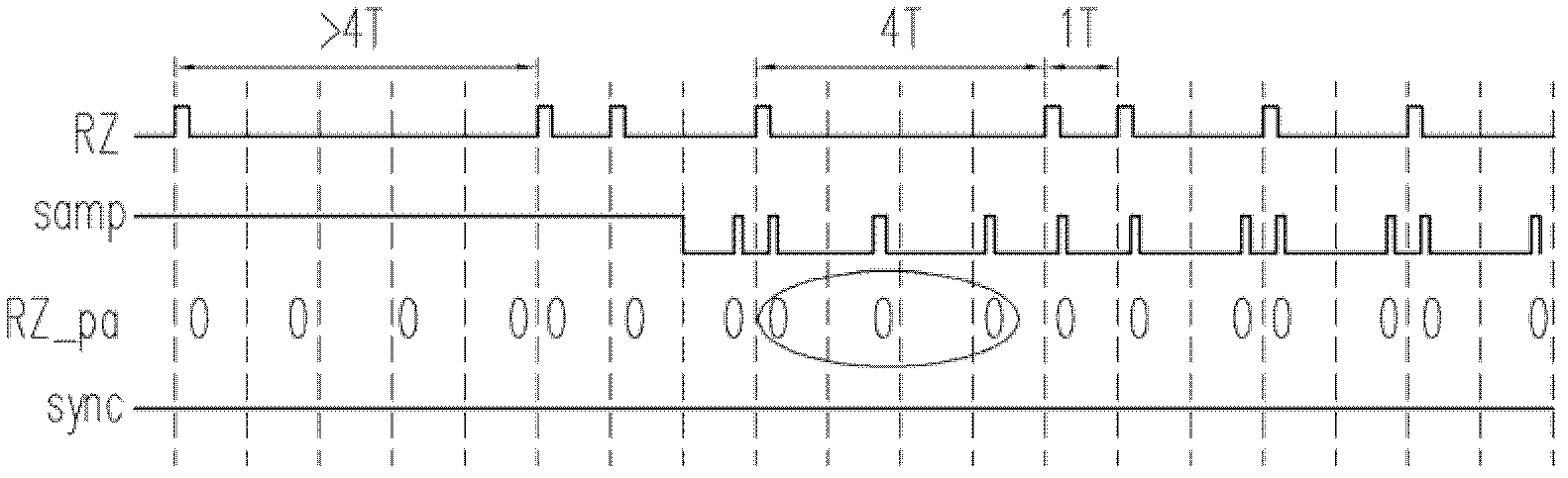
[0074] In operation, the signal processing unit 410 converts the radio frequency signal RF into a return-to-zero signal RZ. For example, in a preferred embodiment, the signal processing unit 410 includes a high-pass filter 411 and a cutter 412 . Wherein, the high-pass filter 411 filters out high-frequency noise in the radio frequency sign...


PUM


Abstract

The invention relates to a data collecting device and method. The data collecting device comprises a signal processing unit, a frequency locking circuit and a matching circuit. The signal processing unit converts a radio frequency signal into a return-to-zero signal. The frequency locking circuit estimates the minimum interval length according to the return-to-zero signal in multiple detection periods, and generates an enable signal according to the minimum interval length and the return-to-zero signal. The frequency locking circuit confirms whether to correct the enable signal or not according to distribution of multiple enable pulses in the enable signal, and accordingly generates a sampled signal. The matching circuit samples the return-to-zero signal according to the sampled signal, and generates a synchronous signal according to a sampling result. Besides, the matching circuit generates a composite synchronous signal through a virtual signal and the synchronous signal. Multiple row data are collected from the return-to-zero signal through the composite synchronous signal.

Description

technical field [0001] The present invention relates to a data collection device and its method, and in particular to a data collection device and its method for collecting row data in a group cut area. Background technique [0002] Since piracy of digital versatile discs (Digital Versatile Disc, referred to as DVD) is very prevalent, copying will be restricted in discs with a content protection for recordable media (Content Protection for Recordable Media, referred to as CPRM) mechanism, To prevent unlicensed videos and content from being copied. Generally speaking, a burst cutting area (BCA) on an optical disc is an area where copyright-related information is recorded, and it records necessary information for decoding the content of the optical disc. [0003] for example, figure 1 It is a schematic diagram corresponding to the structure of the group cut area in the specification of the optical disc. Such as figure 1 As shown, each row has 5 groups of bytes, and the fir...

Claims


Application Information

Patent Timeline
Patent Type & Authority Applications(China)
IPC IPC(8): G11B7/005G11B27/30
Inventor 宋昌锦杨斌襁
Owner SUNPLUS TECH CO LTD
Why Eureka
Try Eureka