Electronic device and connecting seat
A technology of electronic equipment and connection base, applied in the field of electronics, can solve the problem that electronic equipment cannot be used underwater, and achieve the effect of preventing short circuit
- Summary
- Abstract
- Description
- Claims
- Application Information
AI Technical Summary
Problems solved by technology
Method used
Image
Examples
Embodiment 1
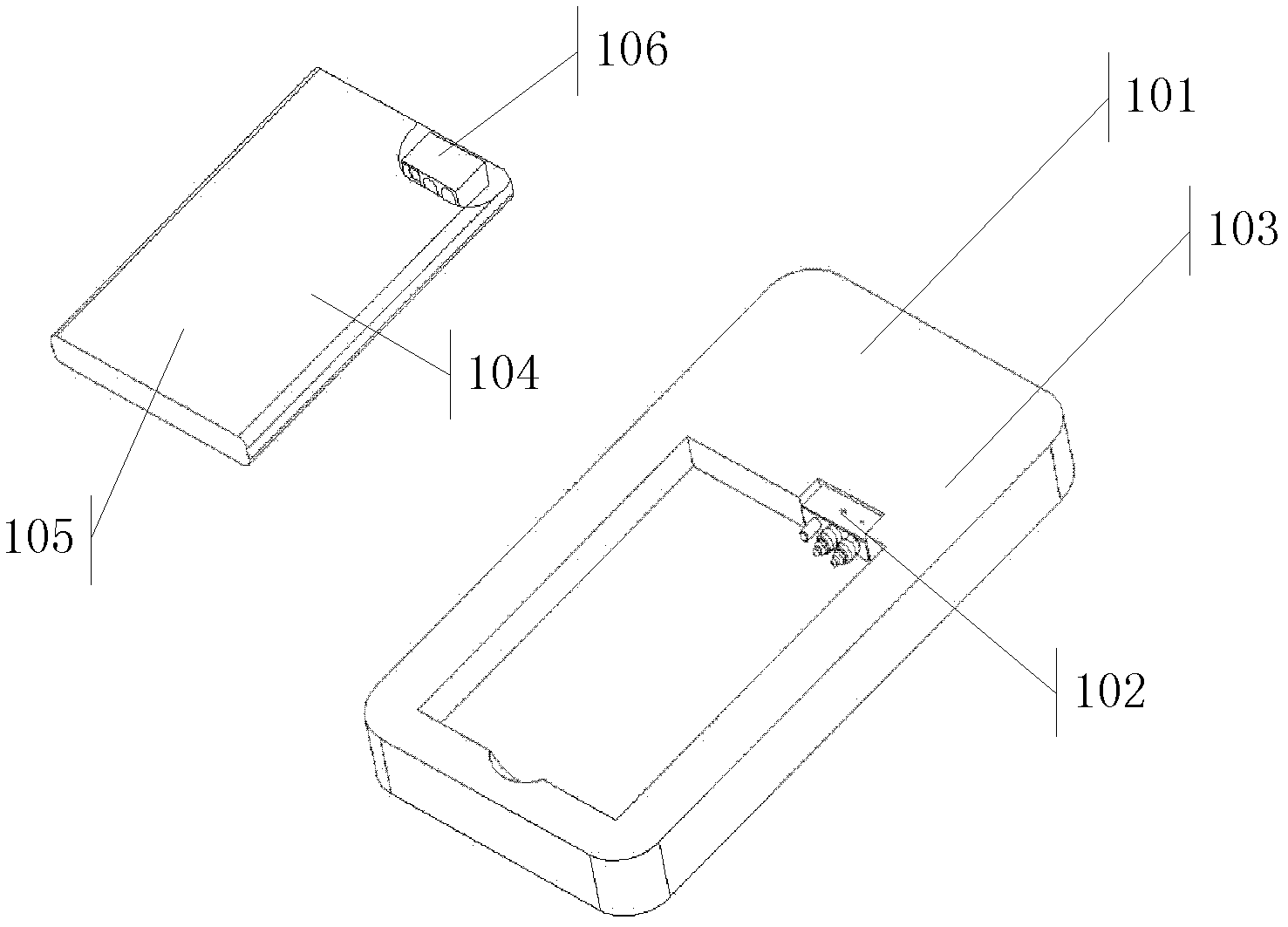
[0038] Please see figure 1 , figure 1 An electronic device is described in , and the electronic device includes: at least one electronic component 101 , a connector 102 , a first casing 103 , a second casing 104 , a battery core 105 , and a connection seat 106 .
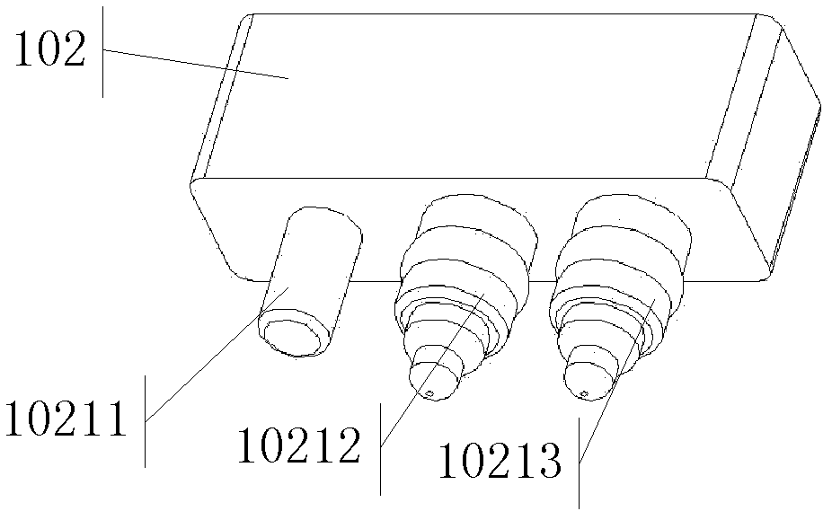
[0039] Wherein, the connection head 102 has a body 1021 and at least one plugging angle disposed on the body 1021 , wherein the body 1021 of the connection head 102 is connected with at least one electronic component 101 .
[0040]The first housing 103 , the first housing 103 is used to seal at least one electronic component 101 and the body 1021 of the connector 102 , so that at least one insertion angle of the connector 102 is exposed outside the first housing 103 .
[0041] The second housing 104 .
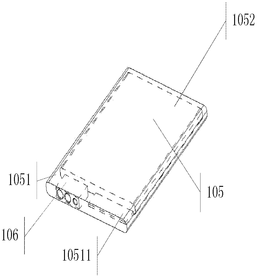
[0042] The battery core 105 is disposed in the second case 104 such that the second case 104 seals the battery core 105 .
[0043] The connecting seat 106 is arranged in the second housing 104, so that the second h...
Embodiment 2
[0062] In Embodiment 2, an electronic device is also provided, including:
[0063] The first casing 103 .
[0064] At least one electronic component 101 is disposed in the first casing 103 , so that the first casing 103 seals the at least one electronic component 101 .
[0065] The connecting seat 106 is disposed in the first housing 103 so that the first housing 103 seals the connecting seat 106, wherein the connecting seat 106 has at least one insertion hole.
[0066] The second housing 104 .
[0067] The battery core 105 is disposed in the second case 104 such that the second case 104 seals the battery core 105 .
[0068] A connector 102, wherein the connector 102 has a body 1021 and at least one plugging angle disposed on the body 1021, wherein the body 1021 of the connector 102 is connected to the battery core 105, and at least one plugging angle is used for corresponding insertion into the connection seat 106 in at least one socket.
[0069] Wherein, in the process t...
Embodiment 3
[0074] Embodiment 3 describes a connector, wherein the connector includes:
[0075] The connection head 102 , the connection head 102 has a body 1021 and at least one insertion angle disposed on the body 1021 .
[0076] The connection base 106, the connection base 106 includes switch contacts 1061, positive contacts 1062, negative contacts 1063, a non-metallic sealing structure 1064, and a first insertion hole 10611 corresponding to the switch contacts 1061, and the positive contacts 1062 corresponds to the second insertion hole 10621 , and the third insertion hole 10631 corresponds to the negative contact 1063 , wherein the switch contact 1061 is sealed by a non-metal sealing structure 1064 .
[0077] Wherein, when the connector 102 is connected with the connection base 106, the connector 102 is inserted into the first insertion hole 10611, the second insertion hole 10621, and the third insertion hole 10631 on the connection base 106, so that the second insertion The connect...
PUM
 Abstract
Description
Claims
Application Information
 - R&D
- Intellectual Property
- Life Sciences
- Materials
- Tech Scout
- Unparalleled Data Quality
- Higher Quality Content
- 60% Fewer Hallucinations
Browse by: Latest US Patents, China's latest patents, Technical Efficacy Thesaurus, Application Domain, Technology Topic, Popular Technical Reports.
© 2025 PatSnap. All rights reserved.Legal|Privacy policy|Modern Slavery Act Transparency Statement|Sitemap|About US| Contact US: help@patsnap.com


