

Brake device for vehicle
A brake device, wheel brake cylinder technology, applied in the direction of brakes, brake components, vehicle components, etc., can solve the problems of inability to detect leakage, inability to quickly determine leakage, etc., and achieve the effect of avoiding misjudgment
- Summary
- Abstract
- Description
- Claims
- Application Information
AI Technical Summary
Problems solved by technology
Method used
Image

Examples
no. 1 approach
[0104] first embodiment
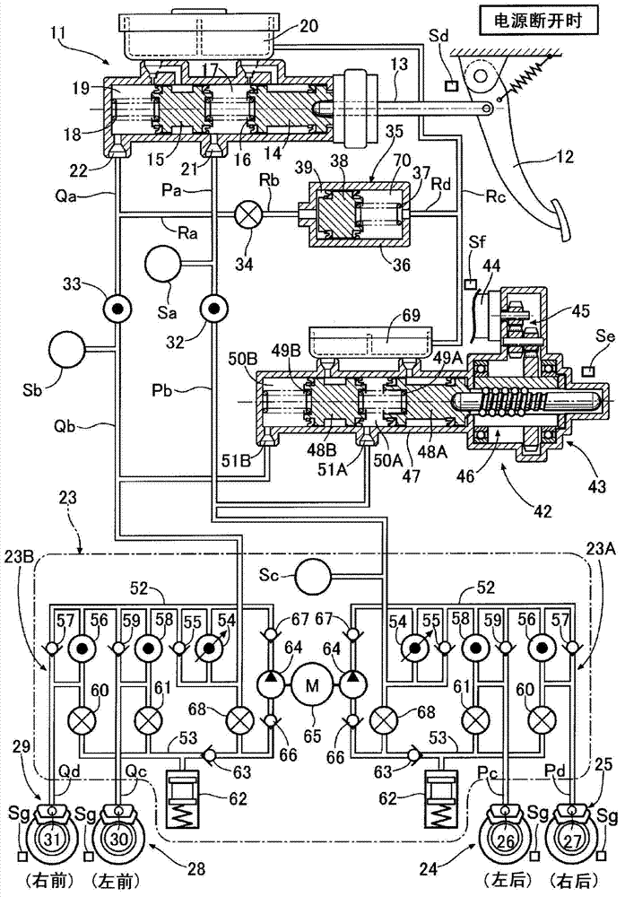
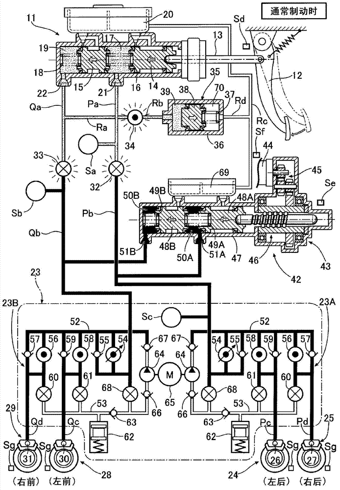
[0105] Such as figure 1 As shown, the tandem-type master hydraulic cylinder 11 has a first piston 14 connected to the brake pedal 12 operated by the driver via a push rod 13, and a second piston 15 arranged in front of the first piston 14. A first hydraulic chamber 17 containing the return spring 16 is defined between the piston 14 and the second piston 15 , and a second hydraulic chamber 19 containing the return spring 18 is defined in front of the second piston 15 . The first hydraulic chamber 17 and the second hydraulic chamber 19 , which can communicate with the reservoir 20 , respectively have a first output port 21 and a second output port 22 . The device 23 and the fluid paths Pc, Pd are connected to the wheel cylinders 26, 27 (first system) of the disc brake devices 24, 25 of the left and right rear wheels, for example, and the second output port 22 is connected via the fluid path Qa. , Qb, VSA device 23 and fluid passages Qc, Qd are connect...
no. 2 approach
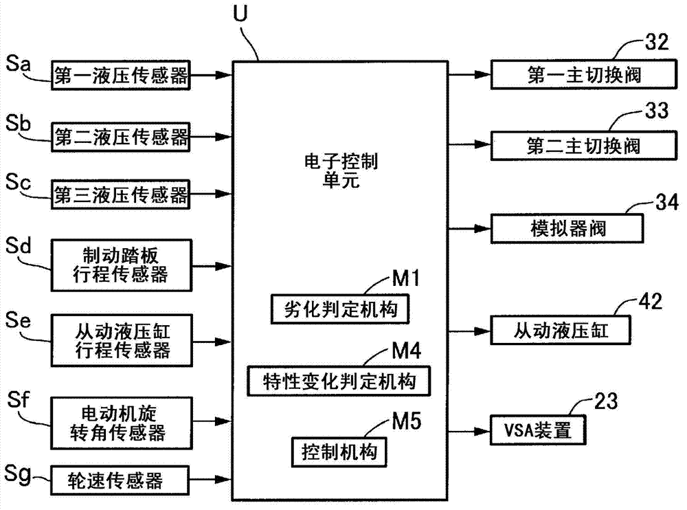
[0157] Such as Figure 8 As shown, the output side of the electronic control unit U is connected with a notification mechanism 71 such as a buzzer, a chime, and a lamp to warn the driver. Moreover, the control mechanism M5 of the electronic control unit U is provided with: a target workload setting mechanism M2 for setting the target stroke of the slave hydraulic cylinder 42 according to the target hydraulic pressure that should be generated in the slave hydraulic cylinder 42; When the leakage is judged, the target operation amount changing means M3 changes the target stroke of the slave hydraulic cylinder 42 set by the target operation amount setting means M2.
[0158] exist Figure 5 , the deviation between the target hydraulic pressure generated in the slave hydraulic cylinder 42 and the actual hydraulic pressure generated by the slave hydraulic cylinder 42 detected by the second hydraulic pressure sensor Sb is calculated according to the pedal stroke-target hydraulic pres...
no. 3 approach
[0167] The deterioration judging means M1 of the above-mentioned first and second embodiments judge the leakage of the liquid path, but the deterioration judging means M1 of the third embodiment judges the blockage of the liquid path. which is, figure 2 The degradation determination mechanism M1 of the electronic control unit U shown is based on the actual stroke of the brake pedal 12 detected by the brake pedal stroke sensor Sd and the actual brake hydraulic pressure generated by the master hydraulic cylinder 11 detected by the first hydraulic pressure sensor Sa. , to determine the blockage caused by foreign matter in the hydraulic passages Qa, Ra, Rb connecting the master hydraulic cylinder 11 and the stroke simulator 35 or the blockage caused by solid connection at the closed position of the simulator valve 34 .
[0168] Next, determination of blockage of the hydraulic passages Qa, Ra, and Rb connecting the master cylinder 11 and the stroke simulator 35 by the degradation ...
PUM
 Abstract
Description
Claims
Application Information