
An Electron Beam Welding Method for Irregular Curved Surfaces

A technology of electron beam welding and special-shaped curved surface, applied in electron beam welding equipment, welding equipment, metal processing equipment, etc., can solve the problems of low efficiency, difficult quality assurance, poor welding effect, etc.

Active Publication Date: 2015-09-09
BEIJING XINGHANG MECHANICAL ELECTRICAL EQUIP
View PDF5 Cites 0 Cited by
  • Summary
  • Abstract
  • Description
  • Claims
  • Application Information

AI Technical Summary

Problems solved by technology

However, when the welding seam of a precision product is a quadratic curve in the vertical plane (z≠0), usually the welding of such a curved seam is completed by manual linear interpolation + intensive point collection. This method is used During the welding process of the parts to be welded, it is necessary to divide the arc weld to be welded into different straight lines for tailor welding, so there are many parts where the arc starts and stops, and the quality of the joint of the two segment welds is difficult to guarantee
This method has low efficiency, poor welding effect, and difficult to guarantee quality.

Method used


Image

  • An Electron Beam Welding Method for Irregular Curved Surfaces
  • An Electron Beam Welding Method for Irregular Curved Surfaces
  • An Electron Beam Welding Method for Irregular Curved Surfaces

Examples


Embodiment Construction

[0047] An electron beam welding method for a special-shaped curved surface, comprising the steps of:

[0048] Step 1: Establish welding seam trajectory curve

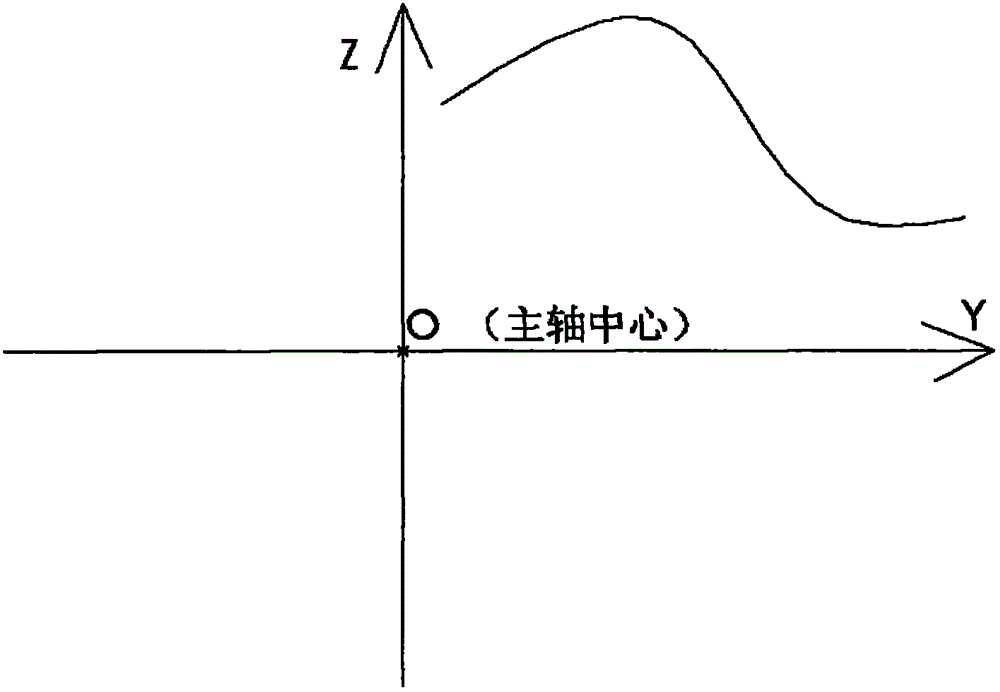
[0049] After the three-dimensional model of the part to be welded is designed (that is, before the product is not processed and welded), the weld plane curve can be established according to the track of the weld to be welded. This step is realized by using existing technology.

[0050] Step 2: Curve Decomposition

[0051] Decompose the curve according to the characteristics of the curve. The decomposition principle is to decompose it into straight line segments and arc segments according to the weld track curve, that is, the weld track curve is composed of multiple consecutive straight line segments and arc segments, and the number of segments to be decomposed is as small as possible. .

[0052] Step 3: Collect points and solve

[0053] The following points are collected for each segment of the curve decomposed in s...


PUM


Abstract

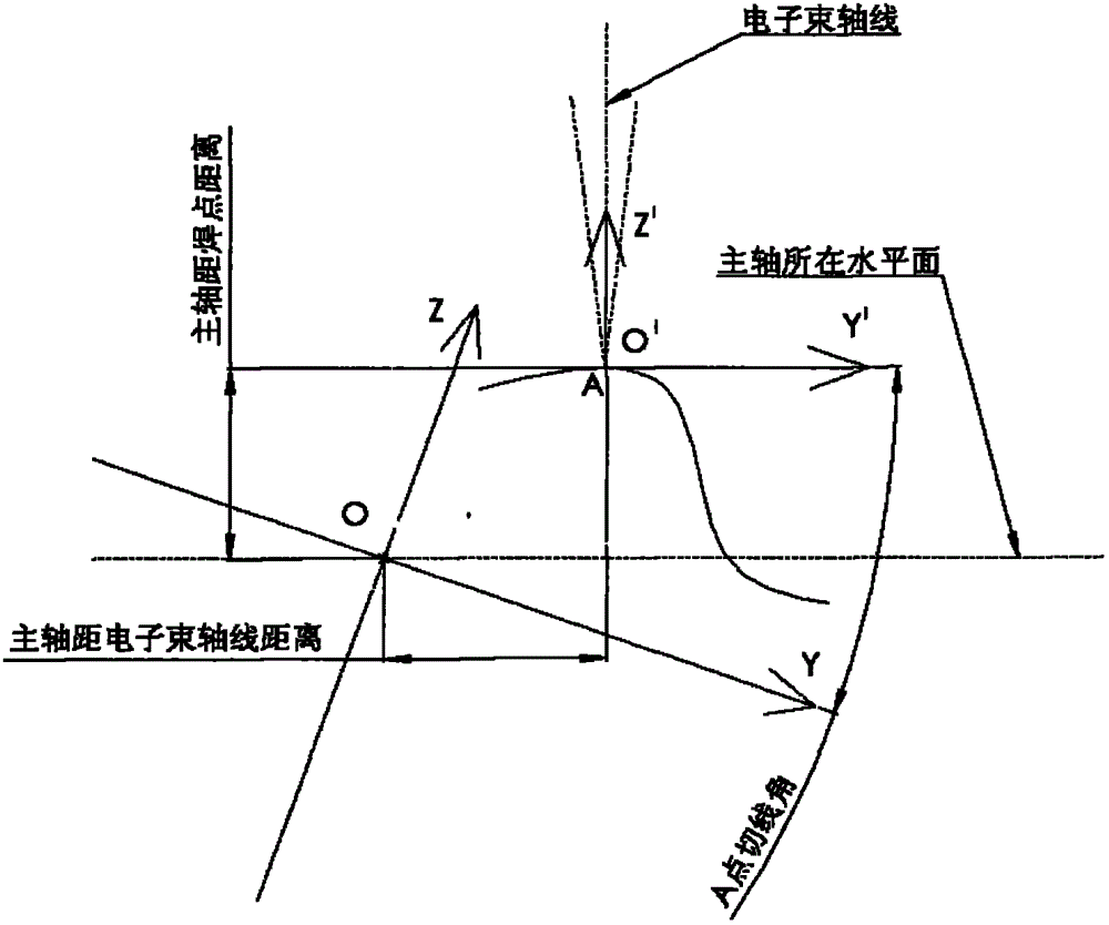
The invention belongs to the electron beam welding field, and particularly relates to an electron beam welding method of a special-shaped surface. The method comprises a first step of building a weld joint plane curve, wherein a trace curve of the weld joint to be welded is generated based on a three-dimensional model of a part to be welded; a second step of decomposing the curve, wherein the curve is decomposed according to the characteristics of the curve, and the decomposing principle is that the curve is decomposed to be straight-line segments and arc segments according to the weld joint curve; a third step of collecting and resolving spots, wherein an electron beam current focusing height, the translation of an electron beam welding machine main shaft on the Y direction, the rotating angle of the main shaft around a C axis and a rotary radius are resolved; and a fourth step of idling for commissioning, wherein a welding procedure is commissioned once in a manner of idling so as to verify the validity of the data in the third step; and if the data are correct, performing the welding with the parameters, otherwise returning to the second step to increase the number of the decomposed curves in curve decomposing. The electron beam welding method has the advantages that a weld joint trace equation is resolved fast and efficiently when the electron beam wielding is performed for a complicated special-shaped surface, and the welding is formed once.

Description

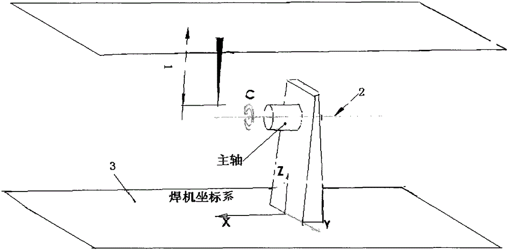
technical field [0001] The invention belongs to the field of electron beam welding, and in particular relates to an electron beam welding method for special-shaped curved surfaces. Background technique [0002] The existing vacuum electron beam welding machine, its electron beam welding working mode is as follows figure 1 As shown, the welding electron beam gun is mostly fixed, but it can be changed in the Z direction by changing the focus current height parameter 1 of the electron beam, and the platform 3 is set at an appropriate position under the welding torch, and the platform 3 can realize three Azimuth linkage, that is, the platform 3 can translate in the direction of X-Y two degrees of freedom, that is, the platform of the welding machine can translate in the direction of X-Y two degrees of freedom, the platform 3 is set with the spindle axis 2, and the parts to be welded are set on the spindle axis 2 , the rotating axis 2 of the rotating main shaft can drive the wel...

Claims


Application Information

Patent Timeline
Patent Type & Authority Patents(China)
IPC IPC(8): B23K15/00
Inventor 朱冬妹熊亮同杨宏青
Owner BEIJING XINGHANG MECHANICAL ELECTRICAL EQUIP
Learn More