
A desktop 3D printing device

A 3D printing and molding device technology, applied in the field of 3D additive manufacturing, can solve the problems of consumables that cannot adapt to large tolerances, deformation of finished products, manual measurement of supports for spinneret winding, etc., to achieve smooth printing experience, stable filament output, and positioning. The effect of improved accuracy

Inactive Publication Date: 2016-05-04
NINGBO HECHUANG RAPID TECH
View PDF1 Cites 0 Cited by
  • Summary
  • Abstract
  • Description
  • Claims
  • Application Information

AI Technical Summary

Problems solved by technology

[0005] The technical problem to be solved by the present invention is to provide a desktop 3D printing molding device to solve the problems that the existing RP cannot adapt to consumables with large tolerances, finished product deformation, spinning winding and manual calculation of support parts. , realize the characteristics of faster printing speed, higher body precision, higher positioning accuracy, and more stable operation.

Method used


Image

  • A desktop 3D printing device

Examples


Embodiment Construction

[0024] Below in conjunction with specific embodiment, further illustrate the present invention. It should be understood that these examples are only used to illustrate the present invention and are not intended to limit the scope of the present invention. In addition, it should be understood that after reading the teachings of the present invention, those skilled in the art can make various changes or modifications to the present invention, and these equivalent forms also fall within the scope defined by the appended claims of the present application.

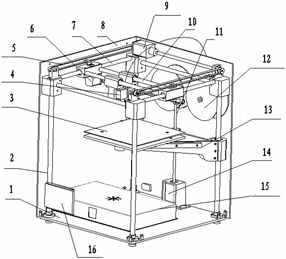
[0025] Such as figure 1 As shown, a desktop 3D printing molding device includes a base plate 1, a frame 2 and a connecting block, the frame 2 is a bottomless cuboid frame fixed on the base plate 1, and the top corner of the upper end of the frame 2 Connecting blocks are installed, and the connecting blocks vertically opposite on both sides are connected by Y-guiding rails 7. A transmission system 5 is installed between the to...


PUM


Abstract

The invention relates to a desktop 3D-printing forming device comprising a base plate, a machine frame and connection blocks. The machine frame is a bottomless rectangular frame and is fixed on the base plate; vertex angles of the machine frame are provided with the connection blocks, adjacent connection blocks are connected with Y-direction guide rails, and transmission systems are arranged above the connection blocks and between adjacent connection blocks; the end of one transmission system at one side is connected to one end of a step motor output shaft, and the other end of the step motor output shaft is connected to the end of the other transmission system at the other side; the Y-direction guide rails which are on two opposite sides are provided with slide blocks, and the top end of the Y-direction guide rails which are on two opposite sides are connected with the transmission systems; X-direction guide rails are arranged between the slide blocks which are two opposite sides, and printing systems are arranged between the X-direction guide rails; the printing systems are connected with wire feeders; the base plate is vertically provided with a linear motor, and output shaft is a Z-direction guide rail; the Z-direction guide rail is connected with one end of an installing beam; and a heating work plate is arranged on the top of another end of the installing beam, and is under the printing systems. Moulding precision is high, processing speed is fast, technology is simple, cost is low, and the desktop 3D-printing forming device can be widely applied in household and the field of teaching.

Description

technical field [0001] The invention relates to the technical field of three-dimensional additive manufacturing, in particular to a desktop 3D printing forming device. Background technique [0002] Rapid prototyping (RP), also known as rapid prototyping technology, is an advanced manufacturing technology developed in recent years. Rapid prototyping technology originated in the United States in the 1980s, and soon developed to Japan and Europe. It is a major breakthrough in the field of manufacturing technology in recent years. Rapid prototyping is a digital forming technology based on the idea of ​​discrete accumulation forming, which automatically and quickly materializes design ideas into prototypes with certain structures and functions or directly manufactures parts, so that product designs can be quickly evaluated and modified, and enterprises can be improved. competitiveness. [0003] RP integrates advanced technologies such as CAD, CAM, CNC, precision servo drive, op...

Claims


Application Information

Patent Timeline
Patent Type & Authority Patents(China)
IPC IPC(8): B29C67/00
Inventor 程永丽张宽同治强李娜丁明勇
Owner NINGBO HECHUANG RAPID TECH
Learn More